Mobirise Website Builder

Stuart No 1
The Lower Cylinder Cover

The bottom cylinder end cover had to be perpendicular to the bore of the cylinder and the hole in the middle needed to be concentric with the bore and parallel with the bore.
Checking this particular casting showed it to be very accurate and so it was possible to use the 3 Jaw chuck throughout. The casing included a useful spigot to aid work holding.
Mobirise Website Builder

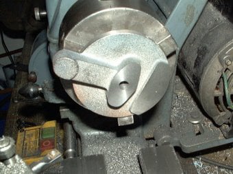
The casting was placed in the 3-jaw chuck with the spigot facing outwards. The spigot was machined to make it concentric to the outside of the casting.
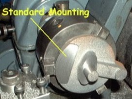
The standard mounting surface was machined by rotating the chuck by hand, because a full revolution of the chuck was not possible.

Mobirise Website Builder

Next the casting was held in the 3-jaw chuck by the spigot.
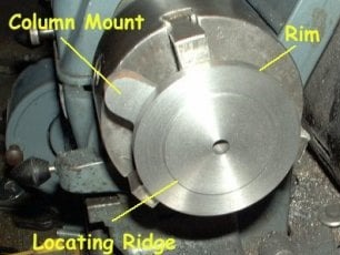
In this setting the back of the column mounting was machined.
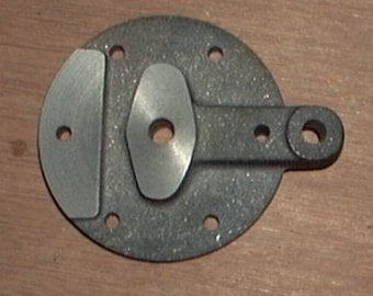
The final diameter of the rim and the locating ridge for cylinder were also formed in this setting. As with the top cover, the outer rim was made 1 mm oversize, so the cylinder lagging would be a flush fit. The finished cylinder was used to check the size of the locating rim. This had to be the best possible fit to locate the piston rod centrally in the bore.

Mobirise Website Builder

Without removing the casting, the piston rod hole was centre drilled, drilled and reamed to final size.
The remaining operations were to drill the 6 bolt holes around the edge. These were marked these out using the spirit level technique (see top cover) but ensuring that the first hole was in the centre of the column mount.
Whilst in the chuck marking the holes, the spigot was machined away.


Mobirise Website Builder

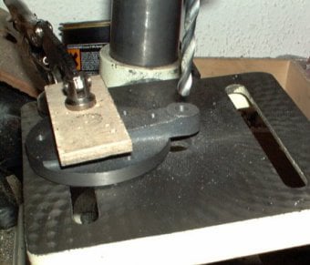
The 8 degree hole for the column mount was drilled by tilting the drill press table. These days a smart phone app is one way to find an exact angle.
Then the hole was centre drilled and drilled to size.

No Code Website Builder