Stuart No 1
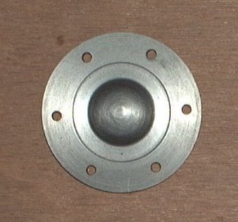
The Upper Cylinder Cover
This component had no critical dimensions although to look right it needed to have accurately spaced holes.
This component had no critical dimensions although to look right it needed to have accurately spaced holes.
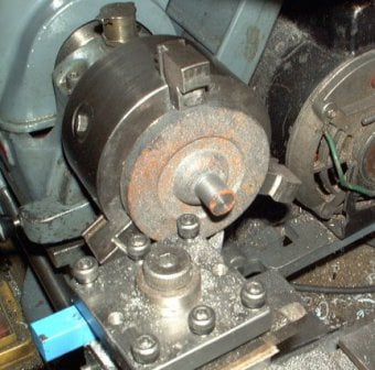
The end cover was mounted in the 3-jaw chuck, with the spigot facing outwards. The spigot was skimmed until it was round. This was done to ensure that the spigot was central when referenced from the outside edge of the casting.
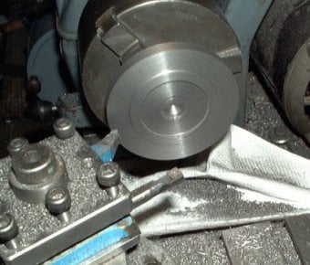
The cover was reversed in the chuck and held by the spigot.
First the shoulder to locate the cover on the cylinder was formed so that the finished cylinder was a close fit. The finished cylinder was used as a gauge.
Clearance for the piston bolt was added using a drill and the boring tool.
The external diameter was finished 1mm oversize, so that it would fit flush with the cylinder lagging.
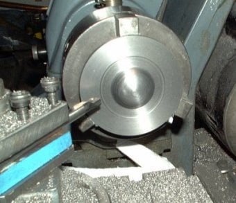
The casting was removed from the chuck and the spigot was sawn off. Then it was placed back in the chuck again to machine the top surface.
The dome was formed by eye using a turning tool, file and finished with some emery cloth.
The screw locations were marked on this side by making a small dent with a lathe tool at the correct PCD. This initial mark was enlarged with a centre punch before centre drilling, and drilling on the drill press.
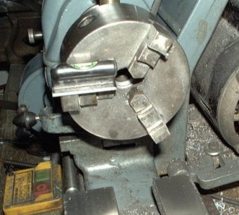
To make 6 evenly spaced holes a small spirit level (cut from an old wood working tool) was placed on each of the chuck jaws (back and front) to give 6 equally spaced marks.
This technique is not 100% accurate, but can give acceptable results if the mating component is drilled to suit.

Mobirise.com