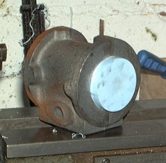
Mobirise Website Builder

Stuart No 1
The Cylinder

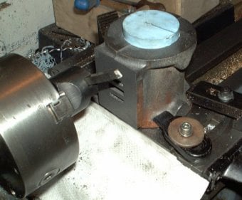
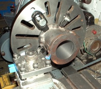
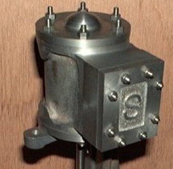
The cylinder is a simple but important component. It is critical that the bore is parallel and round. It is also important to keep one cylinder face perpendicular to the bore so that the piston rod does not bind.
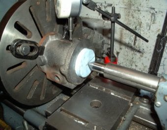
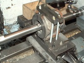
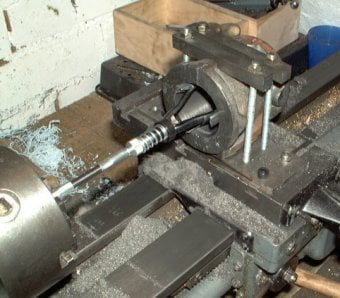
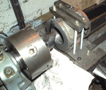
A boring bar between centres was used to cut the cylinder bore to guarantee it as parallel and circular.

Counterboring the hole

First a push fit bung for one end of the cylinder was turned out of a of scrap of plastic. The purpose of this bung was to mark the centre of the outside of the casting and then to use this centre as a reference for the other surfaces. This was necessary because one cannot assume that the cored hole is in the centre.
The plan was to leave the outside wall of the cylinder un-machined so a DTI was used on this surface to centre the casting. 

Mobirise Website Builder

With the casting centred on the face plate, a centre in the tailstock was used to mark the bung.

Dividers were then used to mark the location of the port face from the centre.

Mobirise Website Builder

The cylinder was mounted on the cross slide and squared up against the faceplate. Then a fly cutter was used in the chuck to machine the port face to the scribed line.

Mobirise Website Builder

To bore the cylinder it was clamped to the cross slide.
The previous machining meant that the port face was the correct distance from the cylinder centre.
The centre height of the lathe was 2-1/16th" over the cross slide. Therefore some packing of 5/16 was used to position the cylinder so that the boring bar would be at the correct height.
The cylinder was clamped to the cross slide and squared up against the faceplate. It was left overhanging the front edge of the cross slide, so that one end could be cut in the same setting.
Before taking a cut the cross slide was locked in place using the gib screws to ensure maximum rigidity, to get a perfectly round bore.

Mobirise Website Builder

The lathe was used on a slow speed to take progressive cuts.
The boring blade position was adjusted and measured with the calipers each time, to track progress and the piston ring was used as a guide for the final diameter.
The fine feed was used on the lathe saddle to get a uniform finish.
Once the piston ring fitted, a hone was used in the chuck, to iron out any irregularities in the cylinder bore surface.


Mobirise Website Builder

Before unclamping the cylinder, a fly cutter was used on the overhanging cylinder end, removing about half the total material to be machined from the whole length of the casting.
This was marked as the square end of the cylinder.

Mobirise Website Builder

With the critical machining now done. The cylinder was mounted centrally on the faceplate, with the newly machined as the datum.
The cylinder was turned to the final length in this setting length. The rim was also turned to the final diameter and the end of the port face was tidied up.
Finally the casting was reversed on the faceplate, clocked central again and the other rim turned to size.
The remaining drilling of the cylinder was done once the mating parts had been made.

AI Website Builder