The MK1 Steam Engine
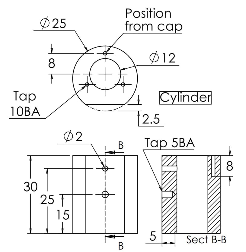
Cylinder
The cylinder was designed to be made using only the 3 jaw chuck but it also required a simple milling operation which could be done in a milling machine or on the lathe with a little ingenuity.
The cylinder was designed to be made using only the 3 jaw chuck but it also required a simple milling operation which could be done in a milling machine or on the lathe with a little ingenuity.
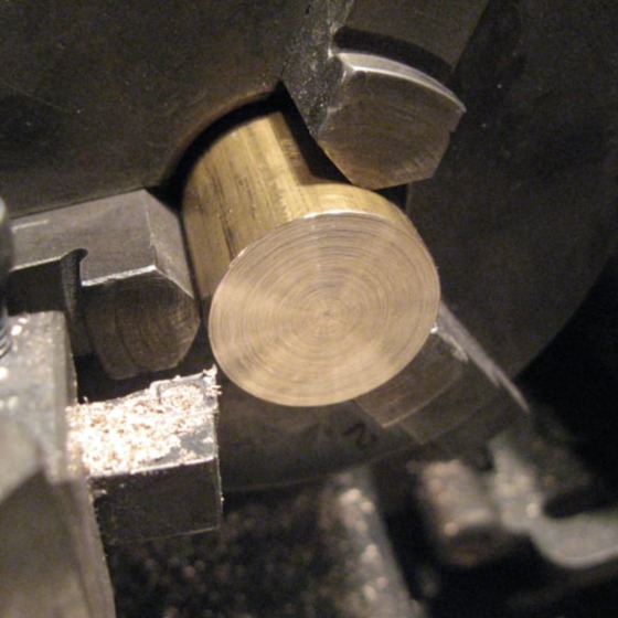
The cylinder is machined from a 1" diameter piece of brass bar. The bar should be cut just over length and then machined to final length (30mm) in the lathe. See this article for details on how to machine to a specific length.
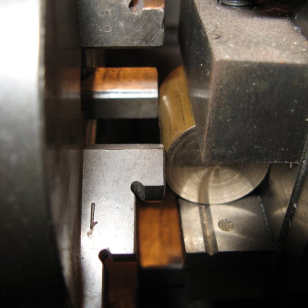
The flat side to the cylinder can be machined using a vertical slide on the lathe or on a mill or using a 4-jaw chuck if you prefer. Another option is to mount a small vice on an angle plate and bolt this to the cross slide.
Whichever technique is used, is it vital the cylinder is square to the cross slide. This can be checked by bringing it up in contact with the tip of the chuck jaws or faceplate.
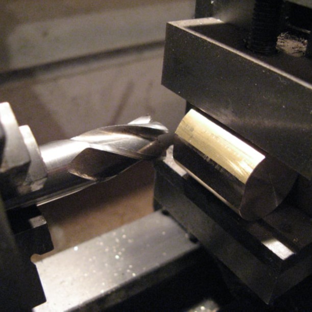
Progressive can now be taken across the side of the cylinder, until 2.5mm of material has been removed.
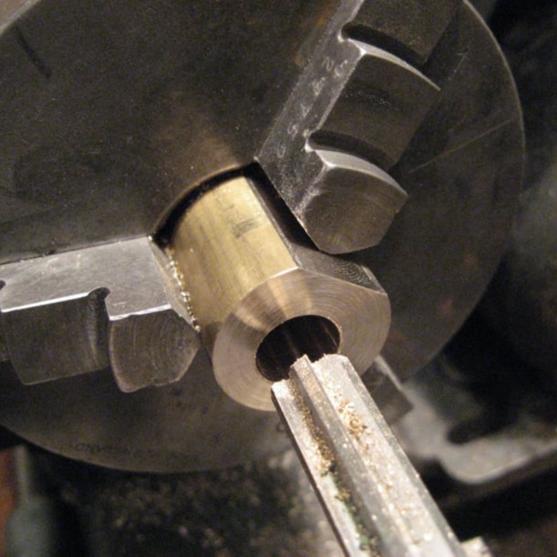
To bore the cylinder it is now mounted in the 3-jaw chuck with the flat face against one of the jaws. The natural offset of the cylinder is what is used to position the cylinder bore in the correct place.
The cylinder can then be centre-drilled, drilled and reamed to the final size of 12mm diameter.
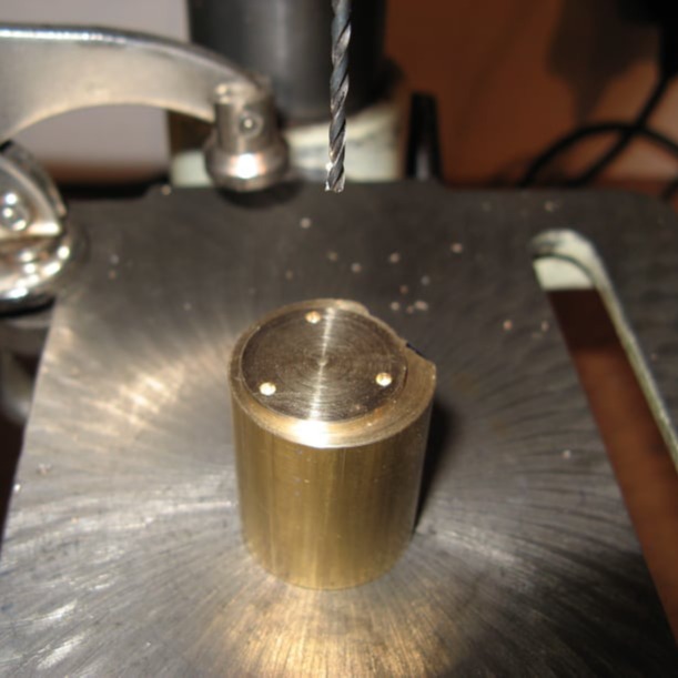
Once the cylinder cap has been made it can be used as a template to mark the cylinder for drilling and tapping.
Note that the cap must be orientated so that no screw holes line up with the steam port in the cylinder.
The pivot hole must be marked out exactly in the centre of the port face.
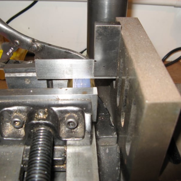
It is then drilled and tapped on the pillar drill. The hole needs to be perpendicular to the port face. To ensure this, the drill table should be checked for squareness and an angle plate and small square used to locate the port face horizontally (see above).
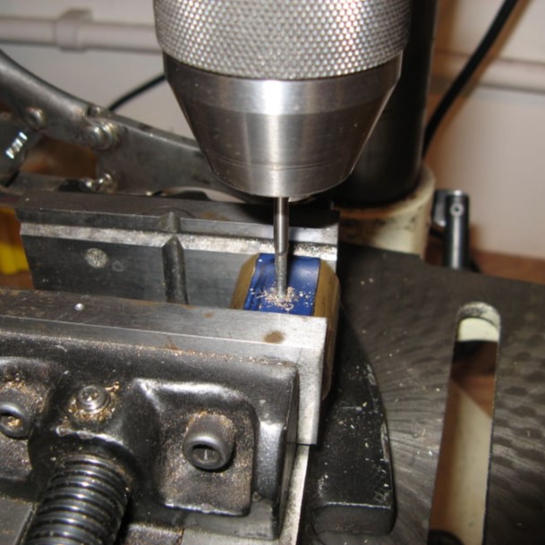
With the cylinder correctly positioned, the vice can be tightened, and the marked hole drilled and tapped.
To tap the hole, the chuck can be turned carefully by hand with the quill spring released.
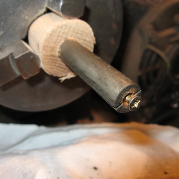
To remove the machining marks form the cylinder a simple cylinder lap made from a wooden dowel can be made.
The dowel should be turned to fit the bore and then drilled to take a small wood screw, then cut 3/4's of the way down the length. The screw can then be used to adjust the diameter of the dowel.
To lap the bore, set the lathe in a slow speed and add metal polish to the lap. Move the cylinder up and down the dowel by hand.
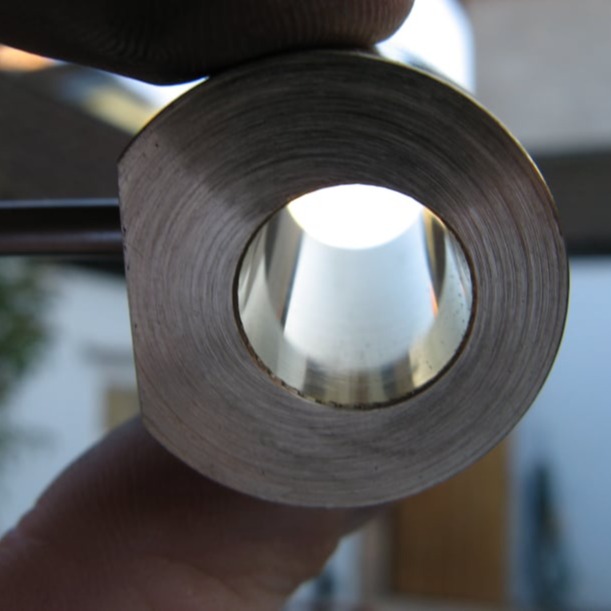
The photo shows the bore with all machining marks polished out.
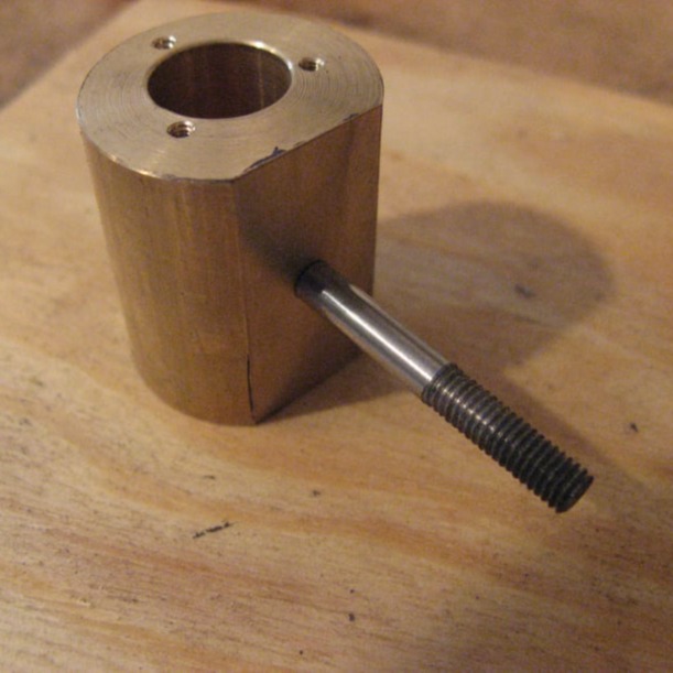
Once the pivot pin has been machined it should be screwed into the cylinder with a dab of Loctite.
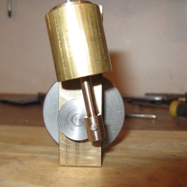
The final operation on the cylinder is to drill the port hole. This is done with the complete engine fully assembled to locate its position accurately.
With the crank rotated to find the extreme oscillations of the cylinder, the cylinder should be positioned so that the exhaust port lines up with the centre of the cylinder. Then a drill used to mark the exact location of the cylinder port through the exhaust port hole.

No Code Website Builder