Mobirise Website Builder

Stuart Victoria
The Piston and Piston Rod

Like any crank web, the cast crank part was designed to hold two shafts at a given offset.
However the two holes would need to be parallel in all planes for it to work without imparting a twisting action into the system; and the holes should be the correct distance apart to match the piston stroke.
Mobirise Website Builder

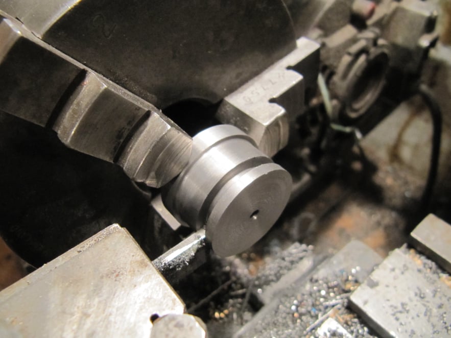
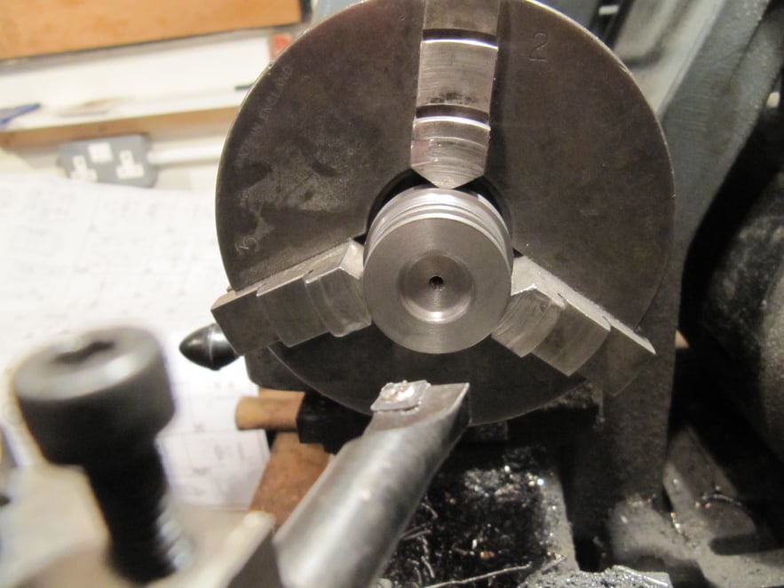
The piston was cut from the cast iron bar stock in one setting in the 3jaw chuck.
The overall diameter was made to suit
the cylinder.
The parting off tool was used to create a groove large enough for the O-ring provided
Before parting the work off the stock the end was recessed with a boring too and drilled and tapped to suit the piston rod.

Mobirise Website Builder

The recess in the crown of the piston was cut using the boring tool.
Then the piston was parted off from the bar stock to create the finished component.

Mobirise Website Builder

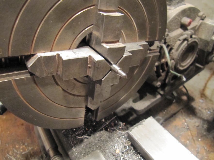
The piston rod was held perfectly central in the 4-jaw chuck so that a concentric shoulder could be turned on the part (a collet chuck could also be used if one is available).
The shoulder was turned with a sharp tool to create a nice square datum face for the piston to pull up to.

Mobirise Website Builder

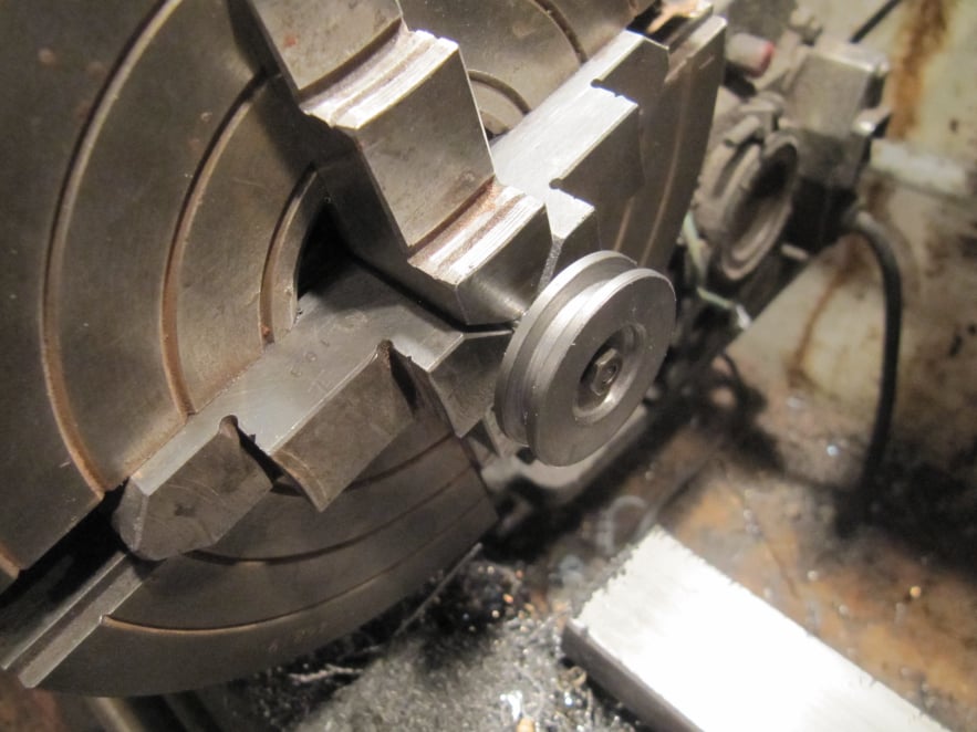
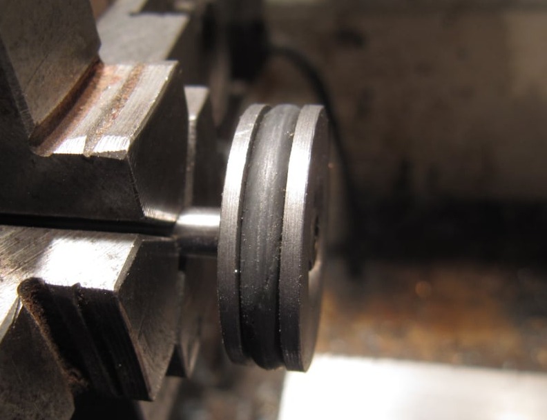
The piston was fitted to the rod before removing from the chuck to check for absolute concentricity. The piston was secured with a lock nut and a dab of Loctite.
In reality there will always be small run out due to assembly variation but it should close enough such that the packing in the piston rod gland and the compliance of the O-ring should allow the engine to run.

Best AI Website Creator