Mobirise Website Builder

Stuart Victoria
The Cylinder

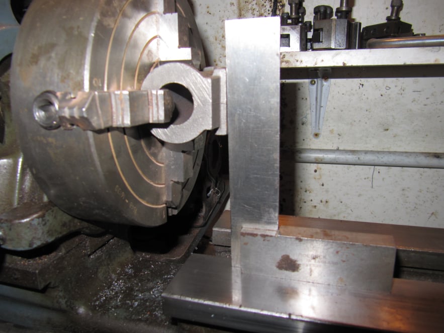
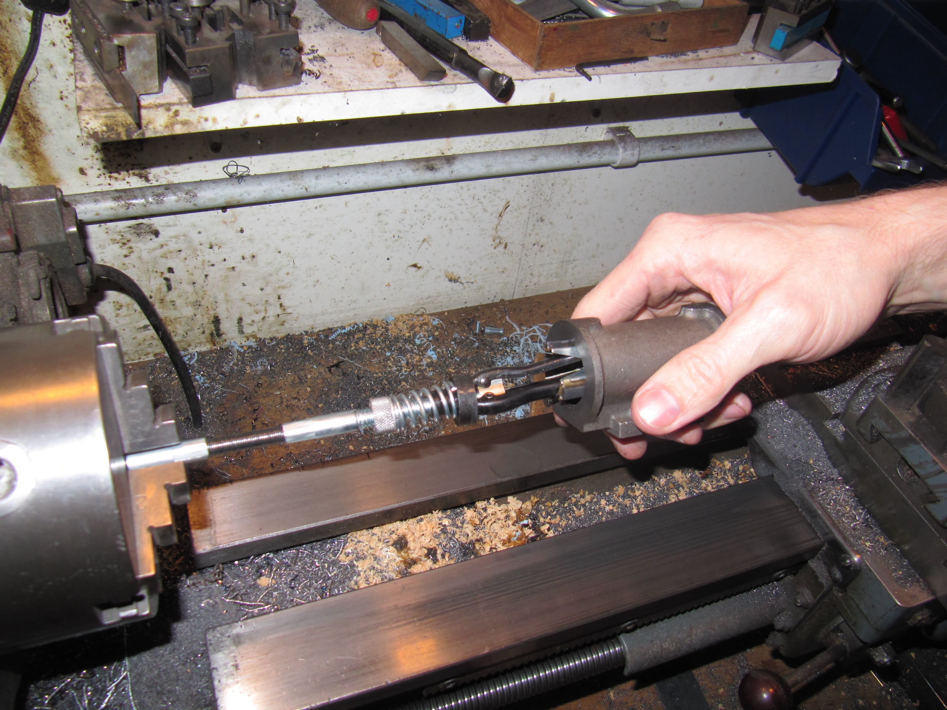
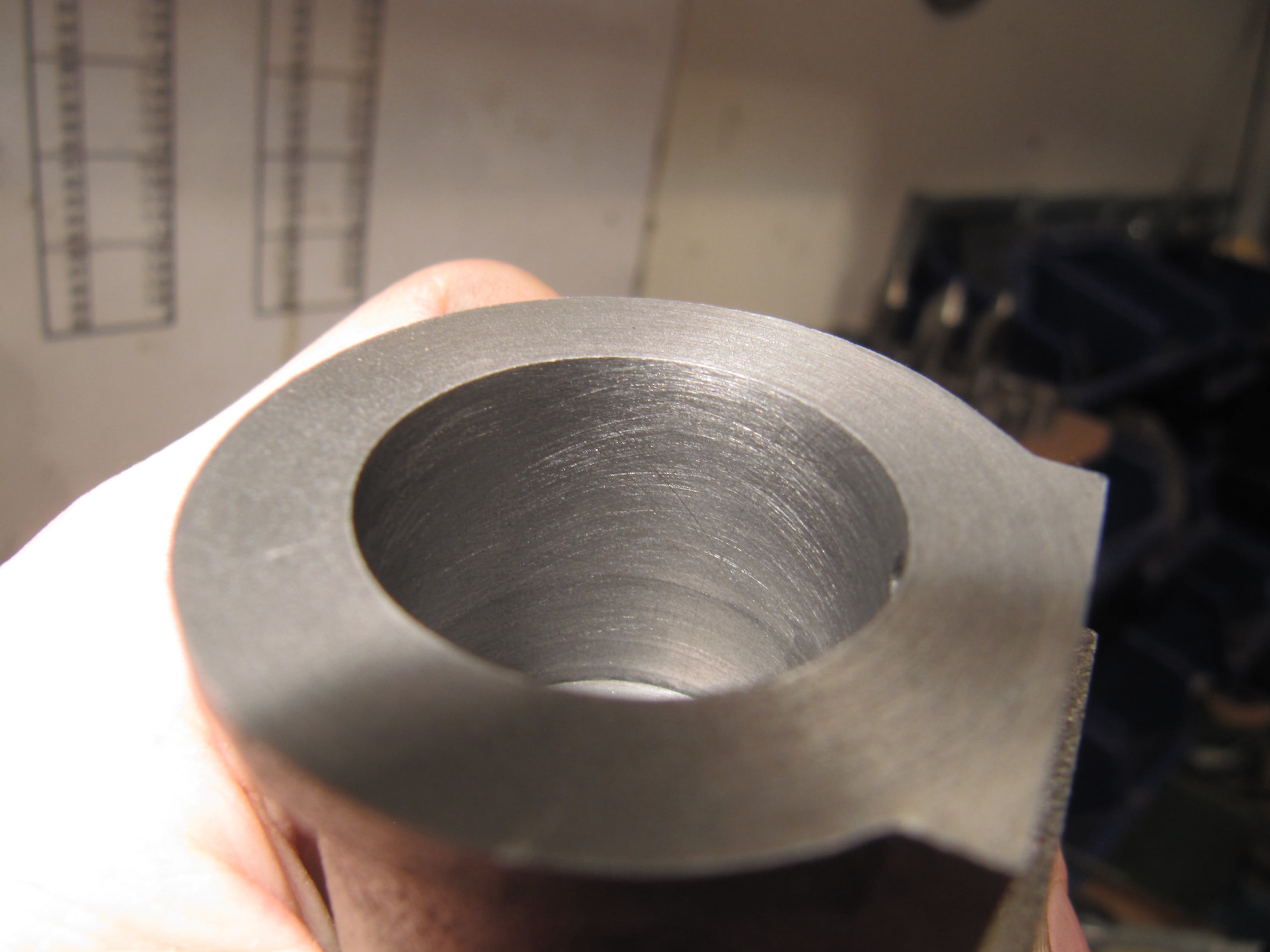
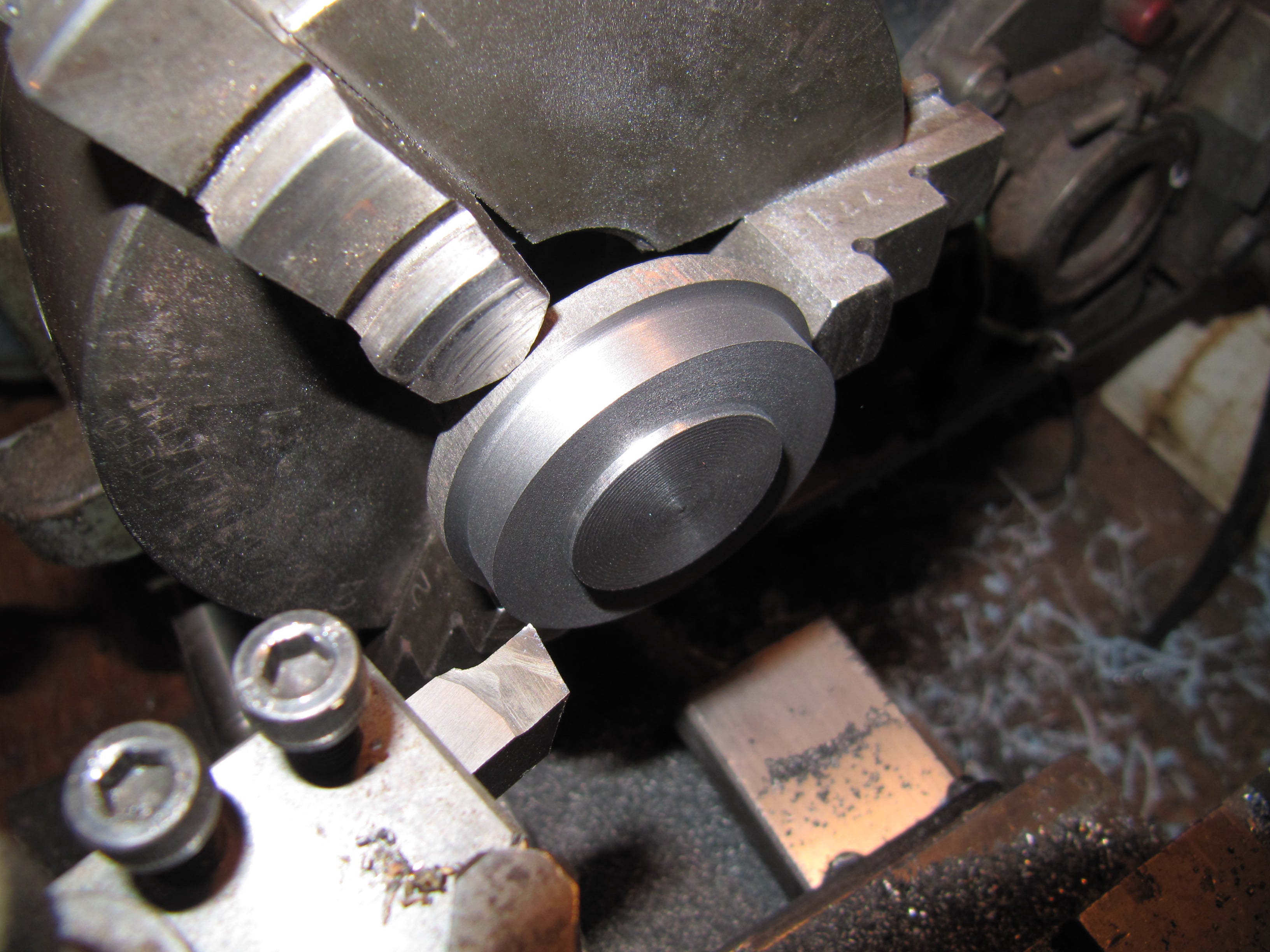
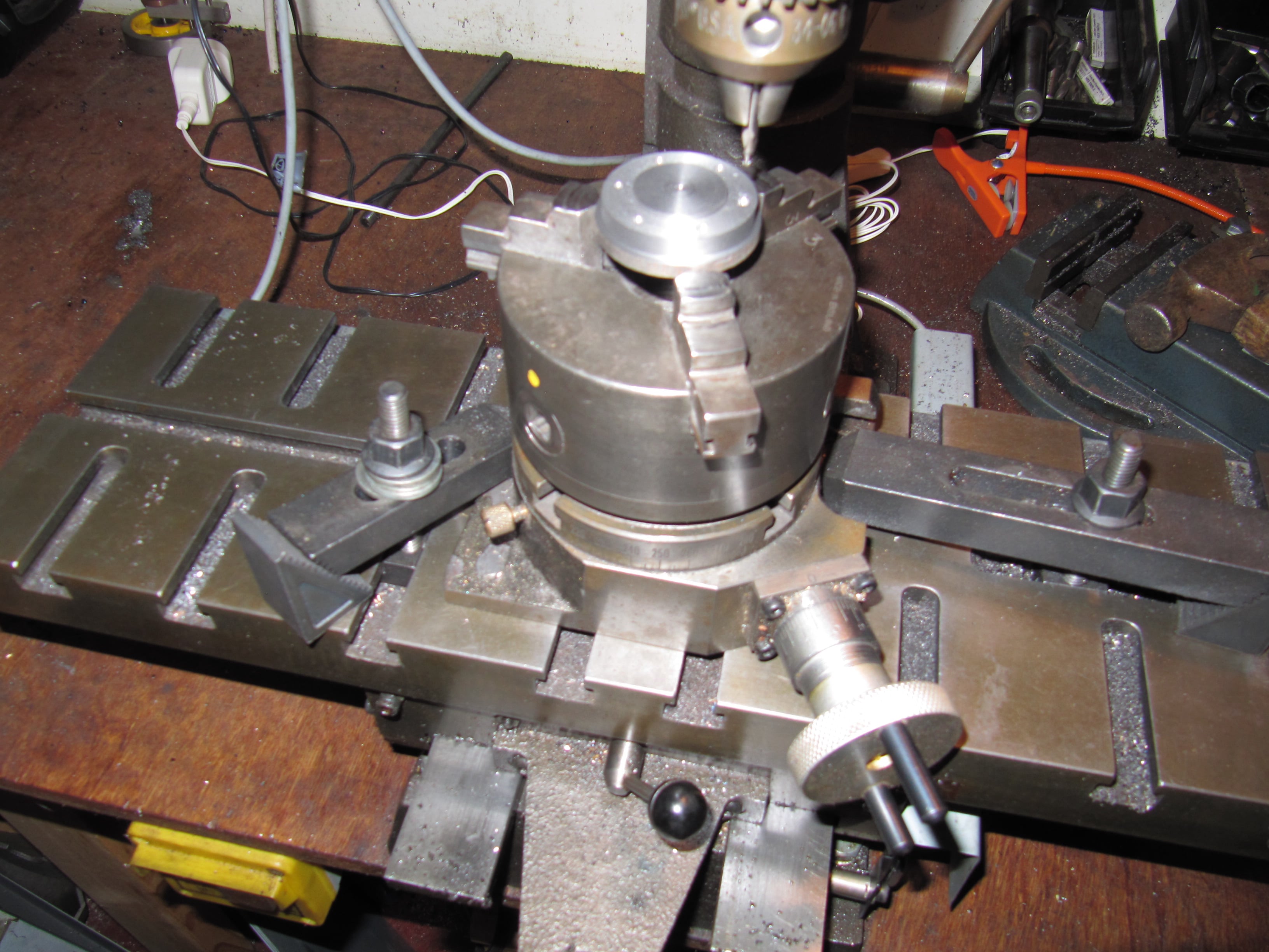
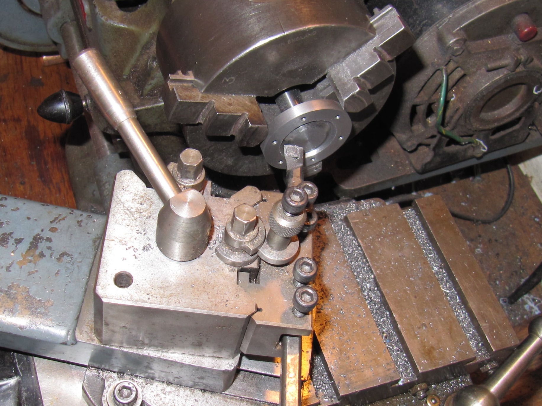
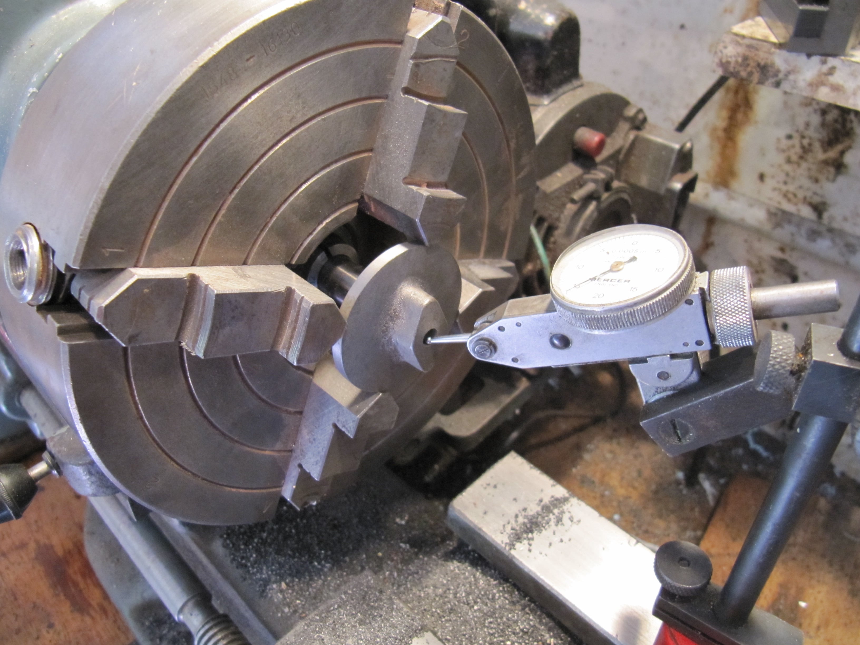
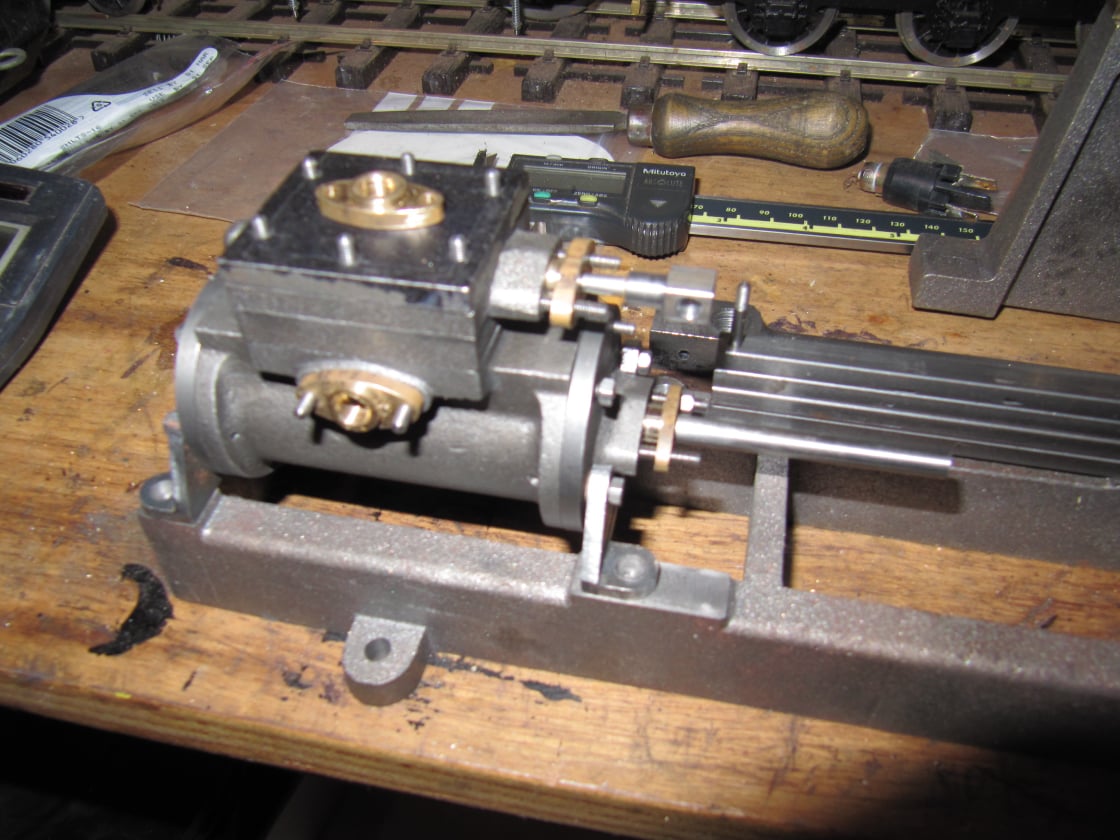
The cylinder was machined before the piston so the latter could be made to suit.
The cylinder bore needed to be parallel and round throughout and the diameter correct enough to suit the O-ring included in the kit.

Mobirise Website Builder

To start the cylinder was clamped in the 4 jaw chuck, checked to be square in both axis using a right angle edge against the lathe bed.

Mobirise Website Builder

In this setting the port face of the cylinder was machined taking the cylinder height down to the correct overall measurement and giving a datum face for further operations.

Mobirise Website Builder

Next, the cylinder was clamped on an angle plate against the faceplate and set to run true as shown using the outer edge of the cylinder as a datum.
In this setting, half the amount to be removed from the cylinder length was machined from the end face.

Mobirise Website Builder

The cylinder was reversed on the angle plate and clocked to run true once more.
The second end face was machined to take the cylinder to final thickness.
Also in this setting the bore was machined to final size. To reduce the risk of tool flex creating a tapered bore, repeated cuts were taken at the same final setting to make sure the cylinder was parallel.

Mobirise Website Builder

A small cylinder hone was used in the lathe at a slow speed to remove machining marks from the cylinder bore.
With the lathe running the cylinder was continuously moved up and down the hone by hand; with liberal amounts of oil in the cylinder.

Mobirise Website Builder

The purpose of the honing was to not only to remove machining marks but also introduce a fine, textured, cross-hatch pattern to the surface to help retain oil in the cylinder wall.

Mobirise Website Builder

The rear end cover was machined in one setting.
Two steps were machined. One to match the cylinder flange diameter and another to match the bore.
The finished cylinder was used to check the fit of both diameters.

Mobirise Website Builder

The chuck was transferred to the rotary table which was used to drill the 6 mounting holes at the correct PCD.

Mobirise Website Builder

The part was reversed in the chuck and held out the correct amount by using a chuck backstop (just visible in the picture). This was just a short length of 12mm bar held in a collect chuck in the spindle and protruding the right amount.
The part was finished to final thickness and the domed centre was shaped using a boring tool.

Mobirise Website Builder

The front cylinder cover casting was held in the 3 jaw chuck; a light centre drill mark in the front cover confirmed that the casting was relatively round. This would mean that clocking on the outside edge of the casting would result is a reasonably centred hole in the part.

Mobirise Website Builder

Following this check, the front cover was mounted in the 4 jaw chuck, held by the boss, and set to run true.
It was also checked to be square on its front face as this face would be left unmachined.

Mobirise Website Builder

Once set to run true the front cover was turned to a diameter to suit the cylinder casting, and to a thickness matching the rear cover.
A step was added to the back face to be a snug fit in the cylinder bore. Finally a central hole was drilled and reamed for the piston rod.
All operations were done in one setting to ensure concentricity.

Mobirise Website Builder

The part was reversed the chuck and set to run true using the centre hole as a reference.
Once again, a backstop was used to hold the part forward of the chuck face whilst still ensuring it was held squarely.
The front boss was faced to take the front cover part to final thickness.

Mobirise Website Builder

The chuck was transferred to the rotary table to drill the mounting holes at the correct PCD.
However this time care was taken to ensure the holes would leave the boss horizontal when the assembly would be mounted on the base.
This was done by clocking the boss and turning the chuck to find the widest point for the first hole. 

Mobirise Website Builder

Once the cylinder covers were complete, they were used to transfer drill the location of the cover studs into the cylinder.
Likewise the steam chest was used to mark out the mounting studs for the chest and cover.
The front cover also had the gland mounting holes transfer drilled once the gland part had been manufactured.

Mobirise Website Builder

Once the steam chest and piston had been machined the cylinder and valve parts were assembled with some oil, to check for a running fit and correct operation of the valve.
The compression was checked by covering both steam ports with one hand and then moving the piston with the valve in both the in and out direction.
Compression should be felt in one direction with the valve pushed in; and in the other direction with the valve pulled out.

Free AI Website Builder