Mobirise Website Builder

Stuart Victoria
The Main Bearings

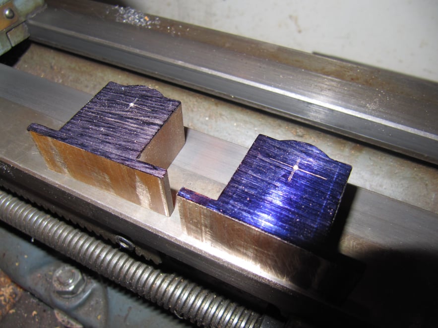
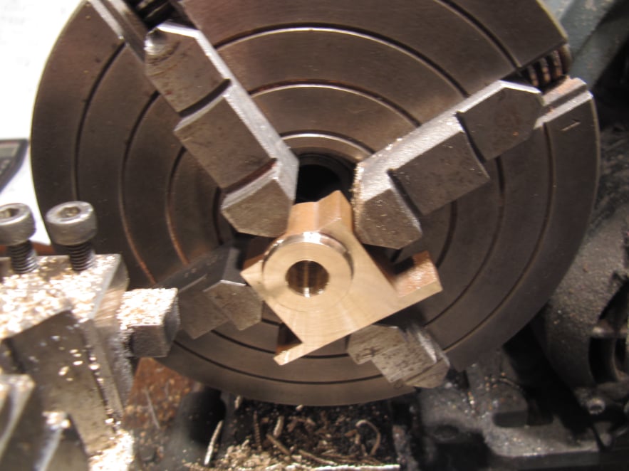
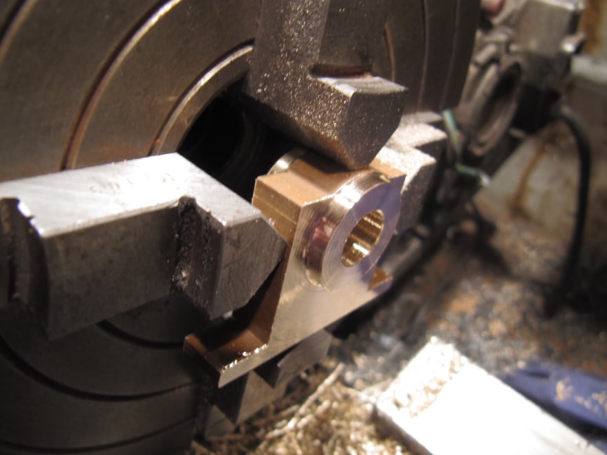
The main engine bearings were machined as a pair to get them as similar as possible.
Care was needed to ensure the hole was square to the base of the bearing otherwise a tilted main axle would cause binding at the cross head.
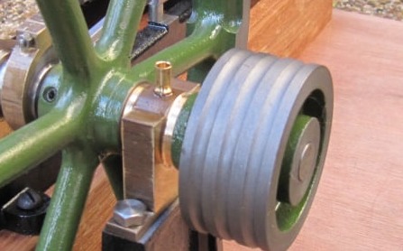
Any difference between the bearing heights was compensated for during final assembly.

Mobirise Website Builder

The two bearing blanks were marked to find the crank position.
Before marking, the underside was filed to remove any burrs and a height gauge was used to find the required offset from this mounting surface.
A centre punch was used to mark the hole location.

Mobirise Website Builder

A note was made of the bearing blank thickness before placing it in the 4-jaw chuck and setting it to run true to the centre marked hole.
A sharp tool was used to tun a shoulder on one bearing face, then the axle hole was centre drilled, drilled and reamed.
The outside of the shoulder was not turned to a specific diameter, rather it was machined until it complimented the top curve of the part.

Mobirise Website Builder

The part was reversed in the chuck and a DTI used to get it running true about the axle hole.
Then the second face was machined including taking the overall part down to final thickness.
Careful marking and drilling was then used to create the mounting holes and a hole in the top for a bearing cup.
As with the cylinder brackets, the mounting holes were positioned so that the hex head of the bolts wouldn't clash with the side of the bearing block.

Best AI Website Creator