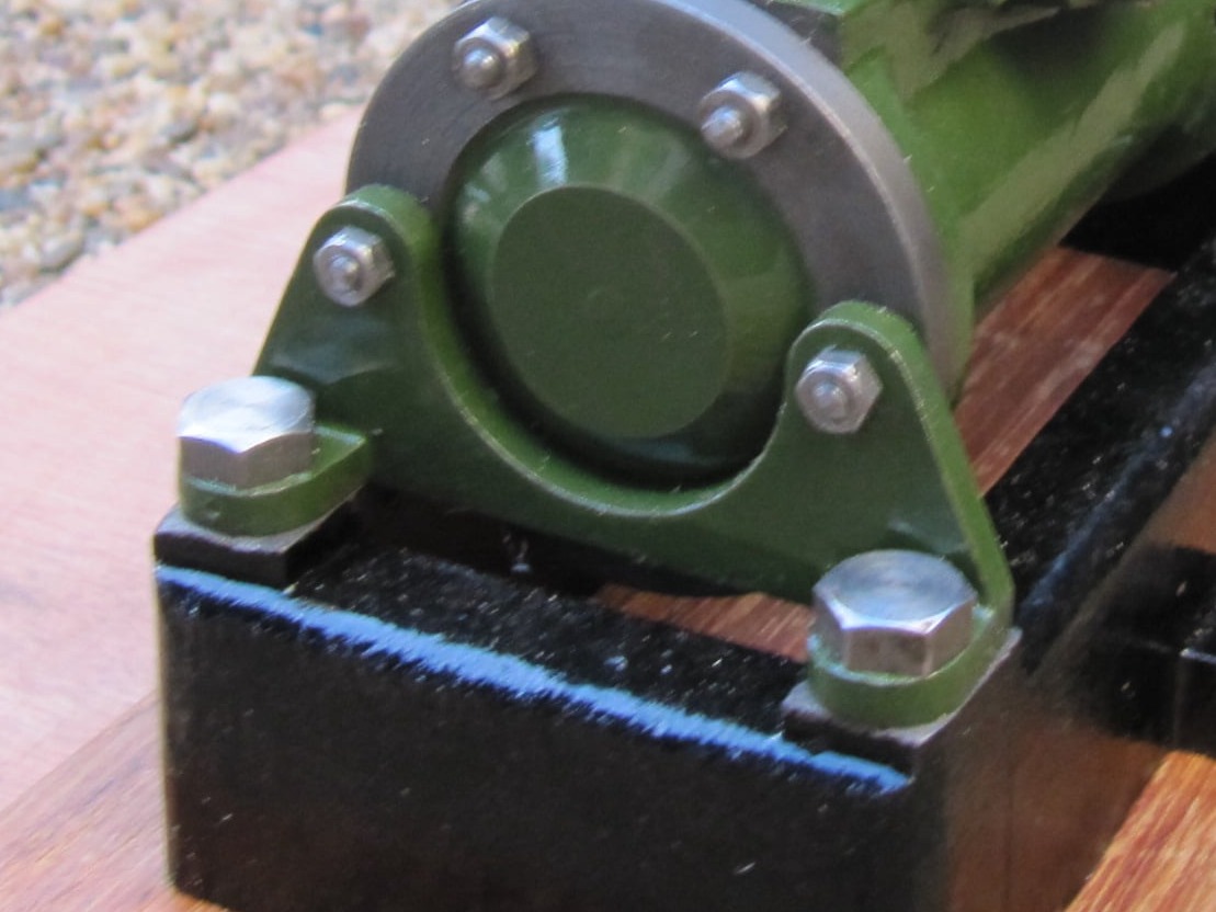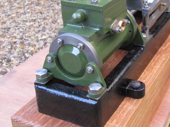
The brackets were machined on the milling machine with some manual filing used to create the rounded corners.
The inner radius was bored on the lathe.
No dimensions were considered critical although it was important to allow room for the mounting bolts to turn without fouling the vertical face of the bracket.
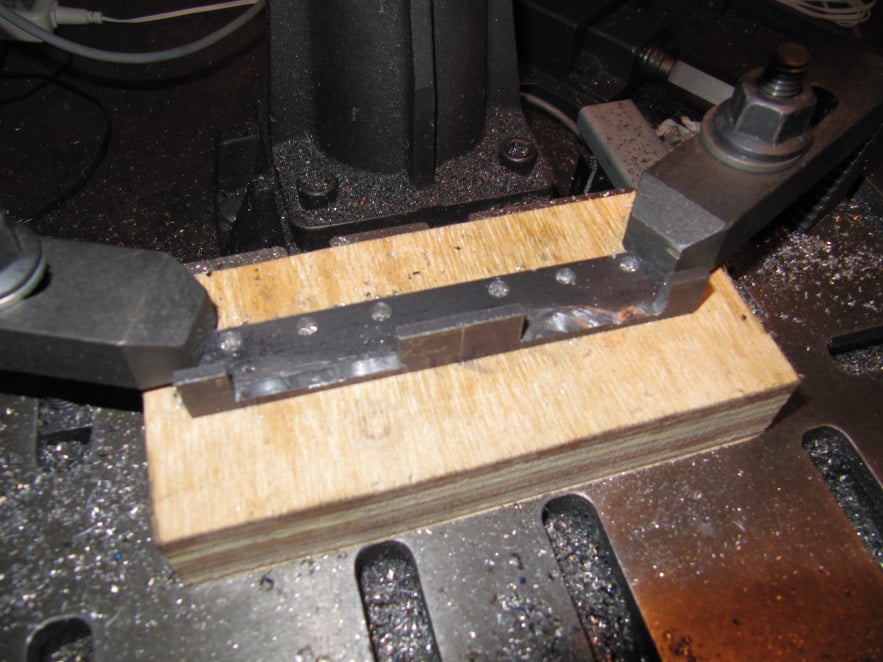
The angle stock provided was set up as shown on the milling table and set to run true to the mill axis.
Holes were co-ordinate drilled for the cylinder mounting studs and also a centre hole for the main bracket cut out.
Also in this setting a section of the angle bar was removed to create the mounting feet.
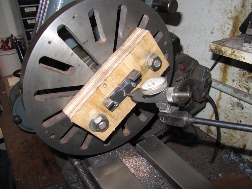
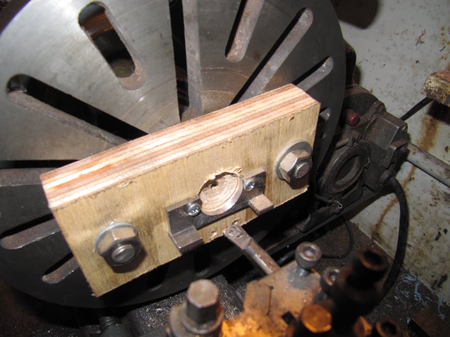
The bracket blanks were separated and each one loaded onto the faceplate as shown. A DTI was used to get them running centrally.
In this setting, the large cut-out was bored to size.
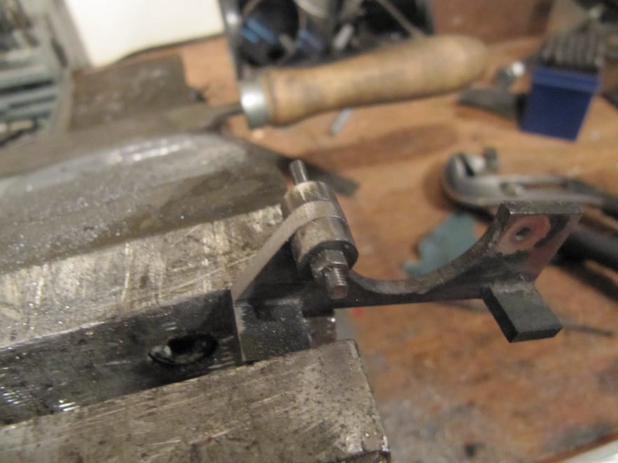
Filing buttons were used to curve the top of the bracket.
The buttons were made from silver steel, turned to suit the radius required and drilled to take a 7BA stud.
The buttons were heated to red-hot and then quenched in water to make them hard.
Then the part was held as shown and filed to shape.
Holes for the feet were marked and then drilled using careful positioning to ensure the given bolts could be turned without fouling the vertical part of the bracket.
More filing buttons were used then round the feet ends.
AI Website Generator