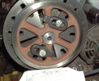
In this setting the rim of the flywheel was machined using a slow speed on the lathe. Also the centre boss was faced, centre drilled, drilled and reamed to final size. Machining the hole and the rim in one setting should provide a flywheel that runs true.
Next the flywheel was reversed on the faceplate. No packing was needed here, as the outside of the rim would not be machined. It was also not necessary to centre anything because only facing operations would be carried out on the rim and centre boss in this setting.
In theory, these two operations should give an accurate, true running flywheel. However the reality is that things like the tightening of the grub screw can bias the flywheel on the shaft and give axial runout. If this is the case then an arbor should be turned and the flywheel mounted on this, secured by the grub screw to be used in the final assembly. Then the rim can be skimmed to get it perfect. Only light cuts should be taken and a slow speed used to avoid tool chatter.
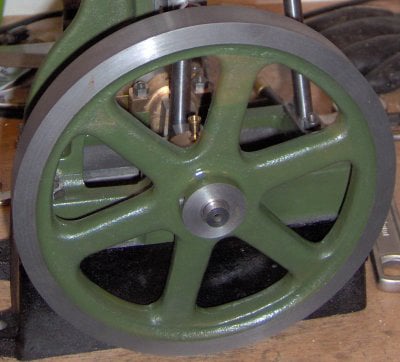
If this skimming is to be done then it is worth painting the spokes first so that a neat line between the rim and the painted spokes is achieved.