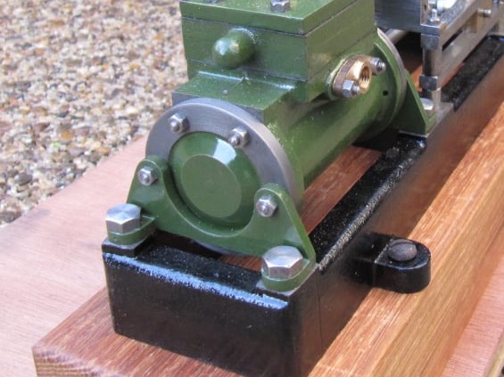
Stuart Victoria
The Flywheel and Pulley
Both the flywheel and pulley were turned using the same process to ensure they would run true once mounted on the crankshaft.

Both the flywheel and pulley were turned using the same process to ensure they would run true once mounted on the crankshaft.
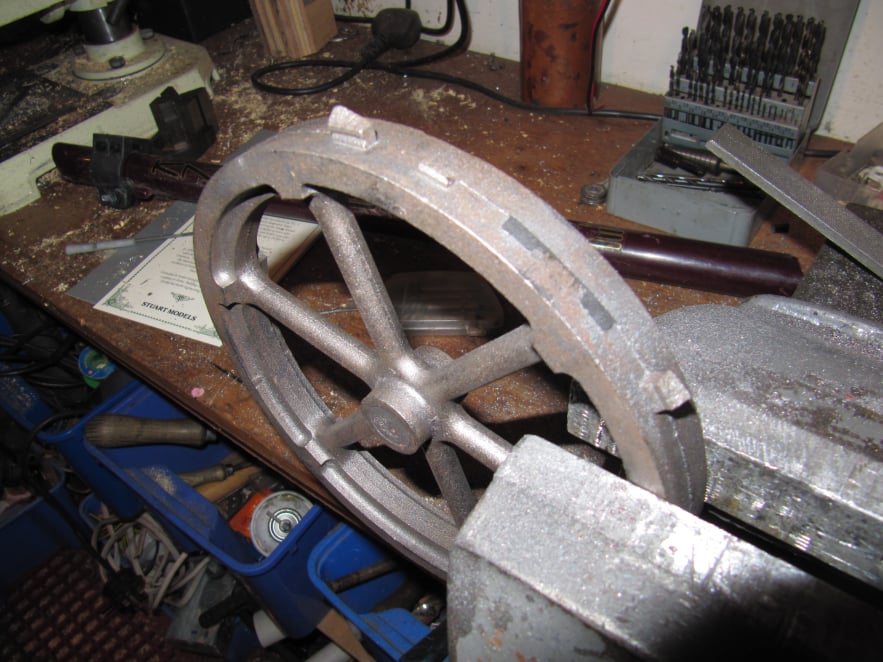
The flywheel was cleaned up with a file to remove the worst of the casting flash.
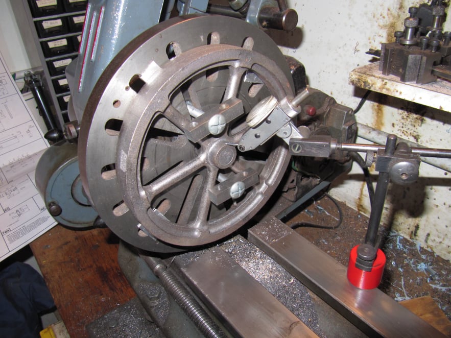
Then the part was mounted on the faceplate as shown and clocked to run true. Note that packing was used behind the flywheel rim to allow the whole outer surface to be machined without damaging the faceplate.
As always an unmachined face was used to centre the part, as machined surfaces would automatically be concentric once finished.
The inside edge of the rim was difficult to clock because of the spoke shoulders so the hub was used to get the flywheel close and then the rim was checked to finally centre the part.
In this setting the centre boss face, the rim and rim edge were all machined to ensure concentricity.
The crank hole was also drilled and reamed to size.
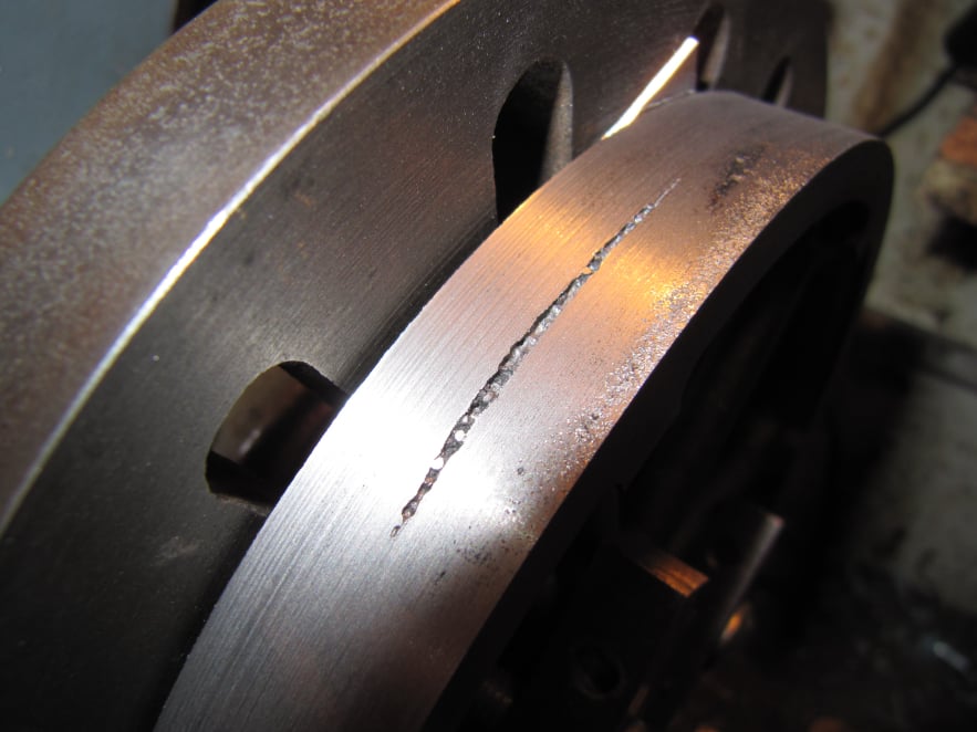
Unfortunately the rim had a defect just below the surface but it was only shallow and was removed by machining the rim a little smaller.
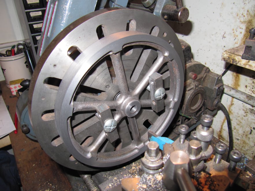
The flywheel was reversed on the faceplate to finish the second side of the rim and the other end of the centre boss.
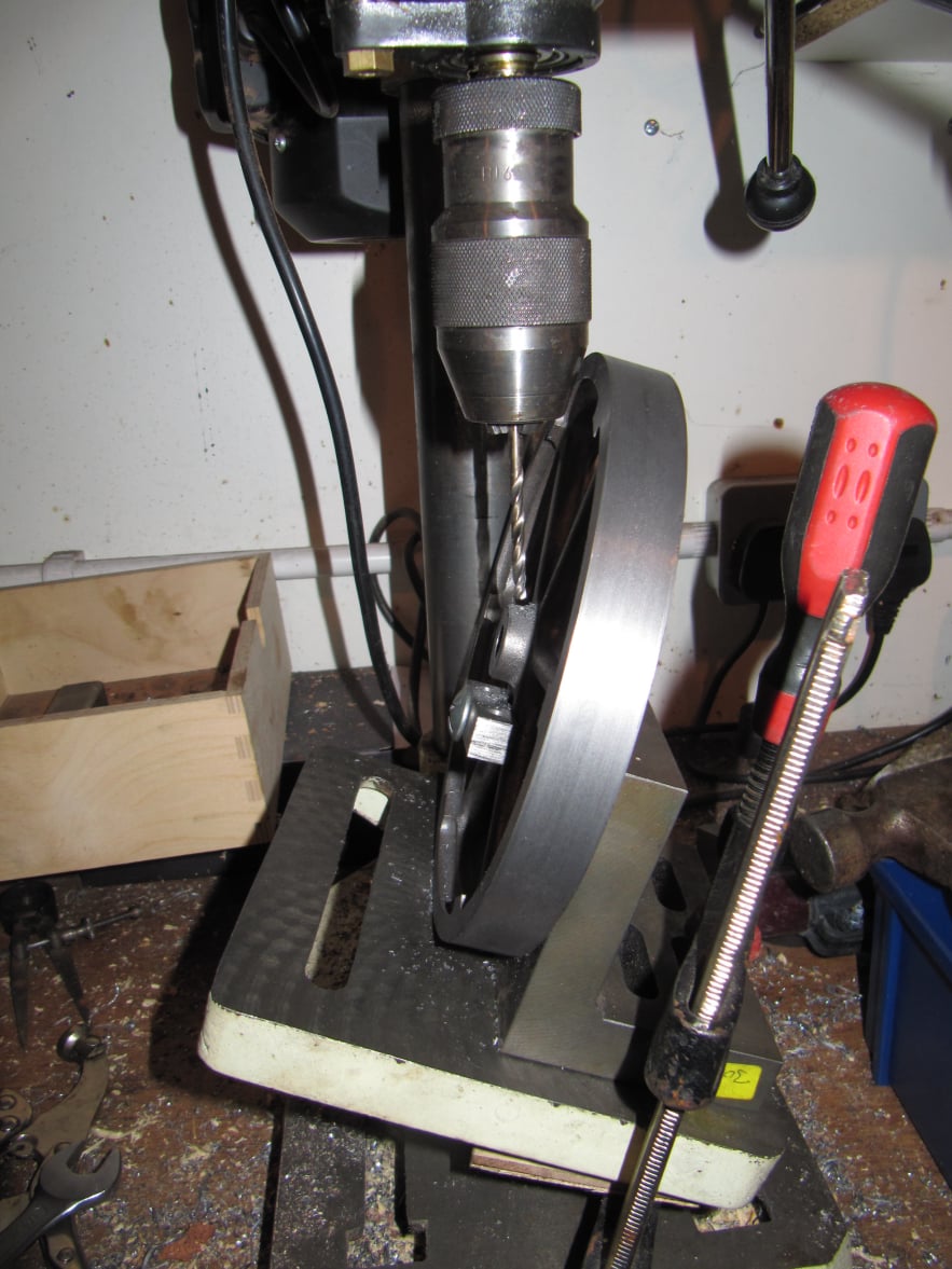
The hole for the grub screw was drilled by clamping the part to an angle plate and tilting the drill table until the chuck was clear of the rim.
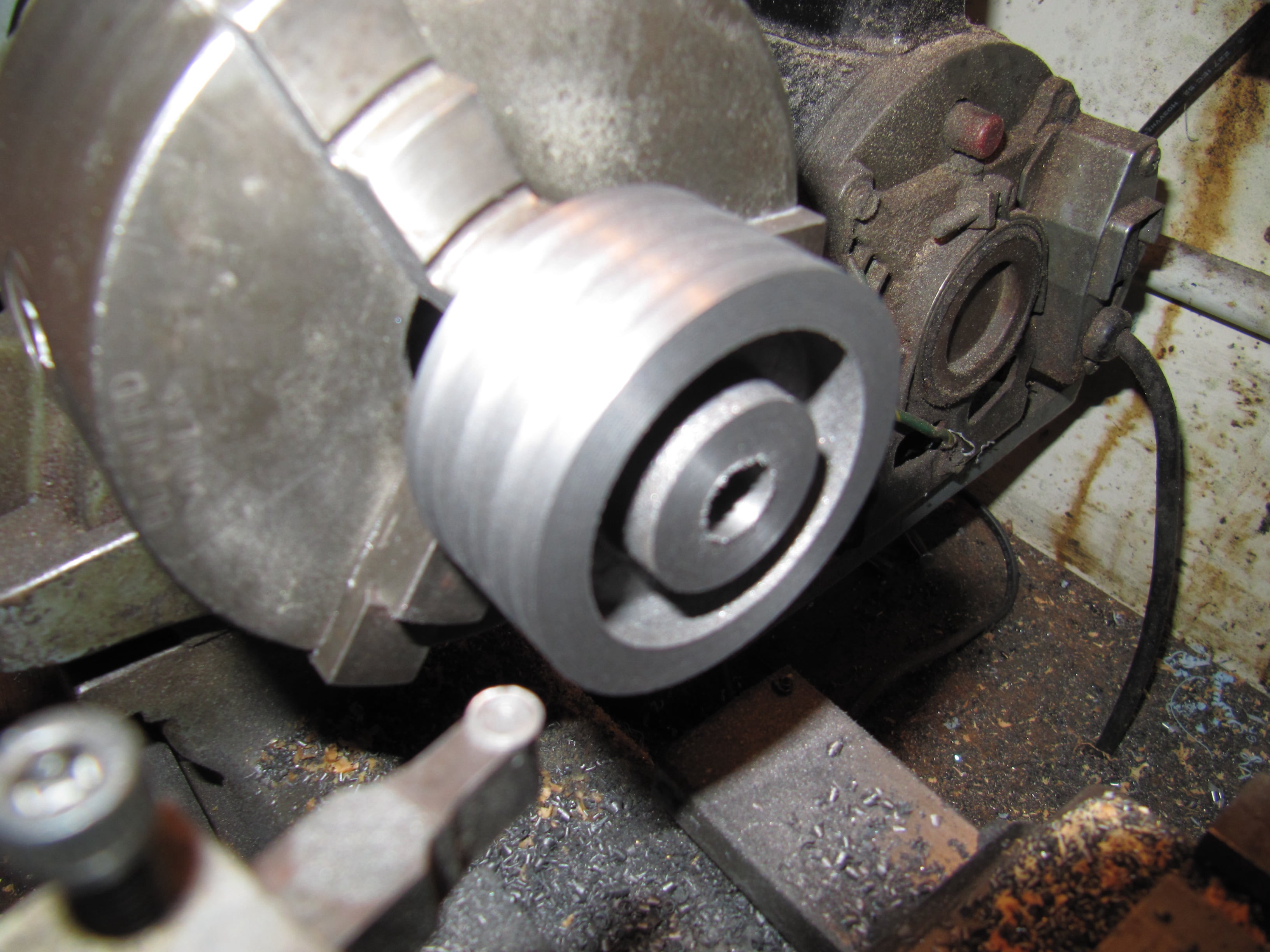
The pulley was machined in two sessions.
First the part was clamped by its largest diameter section and the mounting boss machined to create a parallel cylinder which could then be used to hold the part securely in the chuck.
With the part then held by the boss the centre hole was drilled and reamed. The face of the pulley was turned and the grooves added using a profiling tool.
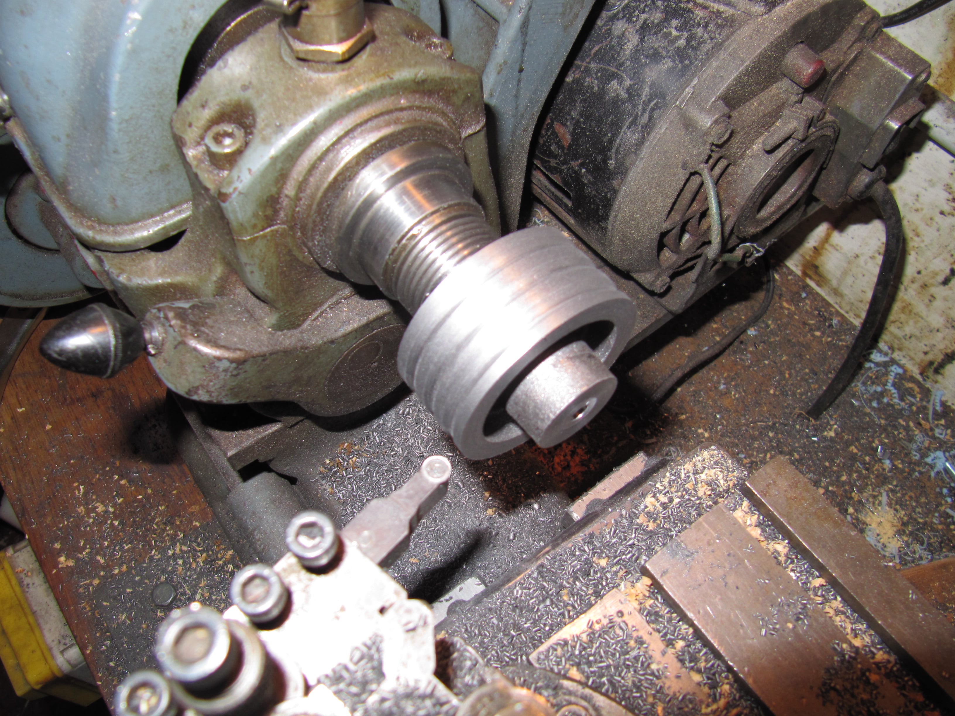
The pulley boss was drilled and tapped to take a grub screw.
Then to finish the part, it was mounted on an arbor running centrally in a collet chuck. Very light cuts were taken to take out any run out in the part.
Similarly the flywheel rim was finished on the arbor to get it exact.
HTML Maker