The cross head was very much machined to suit the parts made so far. It was the final link between the piston and con-rod and so it was machined to ensure that the piston stroke was central in relation to the crank stroke.
The start with a block of steel was machined in the 4-jaw chuck to give the outside dimensions of the part.
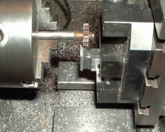
Then a slotting milling cutter was used to cut a groove in the side and top face. This was done as shown using the vertical slide on the lathe.
Equal amounts of material were removed from each side so that it was a snug fit in the slide way which had already been machined on the standard.
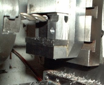
Also in the vertical slide a bull nosed cutter was used to give a rounded edge to the non-functional part of the retaining feature.
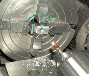
Next the part was centred in the 4-jaw chuck and hole for the piston rod was drilled and tapped.
The position of this hole was approximated from the location of mating parts in the engine. If in doubt then the hole should be drilled so that the dimension shown is too large. The material can always be removed from the back face of the part to get a sliding fit in the standard.
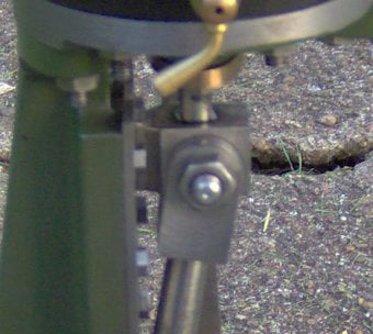
Before drilling and the hole for the cross-head bolt, the part was placed in the assembled engine and checked for size.
First the piston was pushed to the very top and the crank lifted to TDC. The cross-head was then marked though the connecting rod bolt hole. Next the piston was pushed to the very bottom of its stroke and the crank rotated to BDC and the hole position marked again.
The actual hole was then drilled mid way between these locations to ensure that the piston would be centred about the crank stroke.
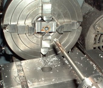
If the crank throw is greater than the piston stroke then this will not be possible and the piston travelled must be increase (by shortening the piston). The cross-head hole was drilled in the 4-jaw chuck to ensure it was square to the sides of the part.
AI Website Generator