The MK1 Steam Engine
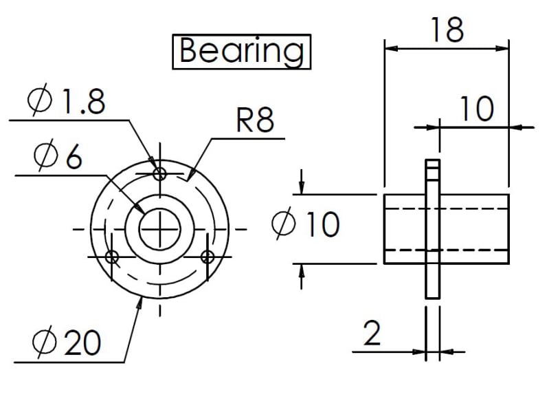
Main Bearing
The bearing provides a running surface for the main axle and one of the shoulders is also designed to give clearance between the crank and the frame.
The bearing provides a running surface for the main axle and one of the shoulders is also designed to give clearance between the crank and the frame.
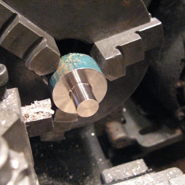
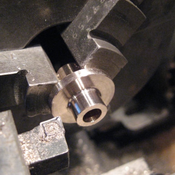
First a chunk of bronze slightly longer than the bearing should be placed in the chuck with enough material sticking out to allow the machining of the 'through frame' part of the bearing and the flange.
The diameter of the protruding section is turned first to be a close fit in the hole in the frame.
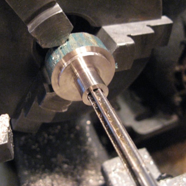
Next the bearing should be centre-drilled and drilled just under final size by 0.1mm. Then a reamer used to finish the hole.
The drilling can use a higher spindle speed (say, 700rpm), however reamers use a slow careful speed, about 100rpm. All holes should be drilled right through.
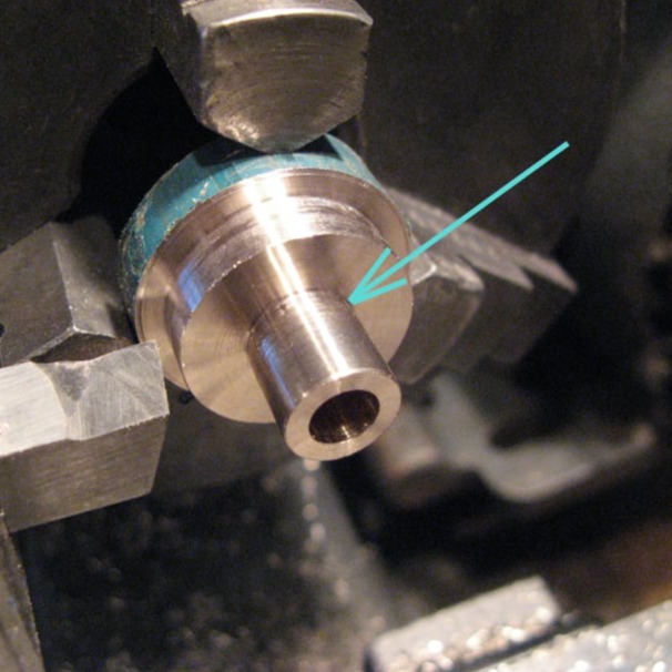
The diameter of the outer shoulder can also be turned in this setting.
A sharp point tool is needed to ensure that there is no radius where shown so that the bearing will sit square in the frame. The length of the protruding part should be finished slightly longer than the width of the frame to ensure the crank does not rub against the frame.
The part can be reversed in the chuck and the protrusion on the other side machined. The length of this protrusion is arbitrary as it only sets the distance between the flywheel and the frame. It can also be left with a radius at the root.
The square shoulder previously cut should enable the part to sit back against the chuck jaws to help everything stay square.
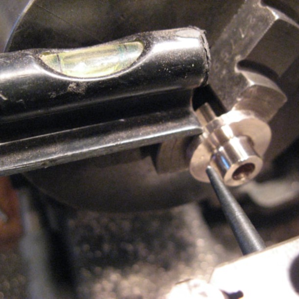
Whilst in this setting the 3 mounting holes are marked out. This can be done approximately by by placing a centre punch in the tool post and using a spirit level on the chuck jaws to create 3 evenly spaced holes.
Hole positions using this method are not perfect, but visually acceptable.
The holes can then be drilled on the drill press

Free AI Website Software