Mobirise Website Builder

Stuart Victoria
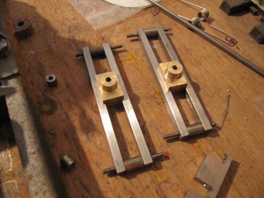
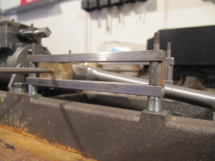
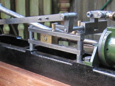
The Cross-Head and Guide Rails

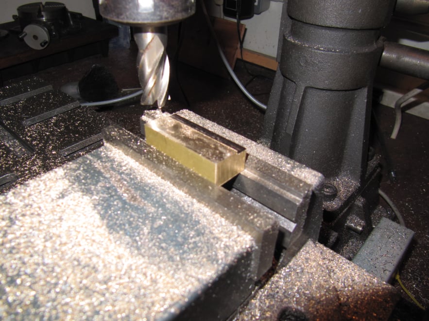
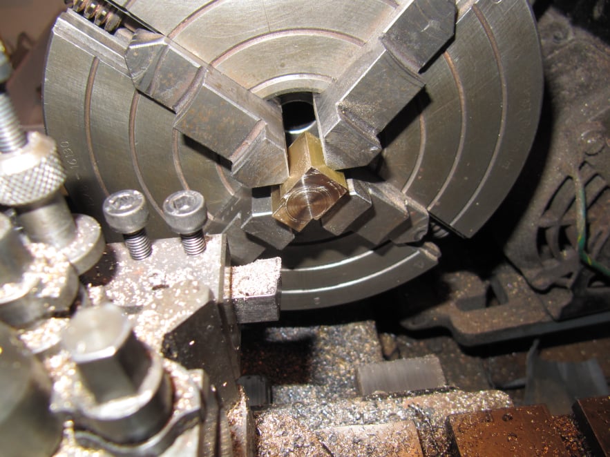
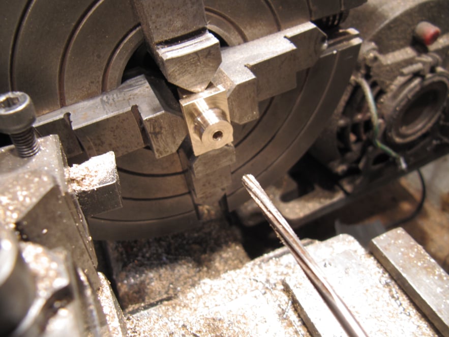
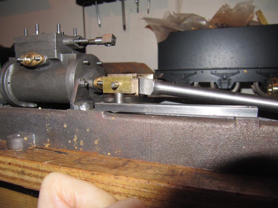
The cross-head parts were machined before manufacturing the guide rails, so that any errors could be compensated for in the guide rail assembly.
The aim being to get a sliding fit with minimum friction.

Mobirise Website Builder

The brass block for the cross-head was mounted in the milling vice; set square to the table and to the x-axis of the machine.
Then a cutter was used to create the required step on the side.
Without changing the vice position or moving the y-axis the part was flipped over in the vice and the second side machined.

Mobirise Website Builder

The brass block was cut in two with a hack saw and then the ends of each part were machined square in the 4-jaw chuck; finishing the part to length at the same time.

Mobirise Website Builder

To finish the cross-heads the 4-jaw chuck was used again to find the centre of the part and to create a through hole and support boss.

Mobirise Website Builder

To make the cross-head a sliding fit in the guide bars, the guide bar spacers were made to be just fractionally longer than the cross-head thickness.
With the parts loose assembled on the bench it was possible to adjust the spacer bushes to get the required fit.

Calculating the support boss height

To get the best running fit of the cross-head / guide bar assembly the engine was partly assembled as shown.
In this set up the guide bar was set to rest on the machined box bed mounting points and the gap up to the cross hear was measured with shims. Then a spacing boss was made and test fitted as shown.

Mobirise Website Builder

Even with this measurement process for the support posts, several attempts were needed to get the engine running with minimal friction.
It seemed that the cylinder was tilted up very slightly towards the crank end of the engine, possibly due to a difference in the the cylinder brackets.

Drag & Drop Website Builder