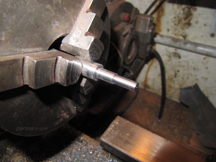
Mobirise Website Builder

Stuart Victoria
The Crankshaft

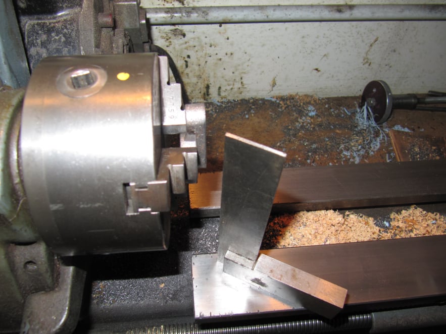
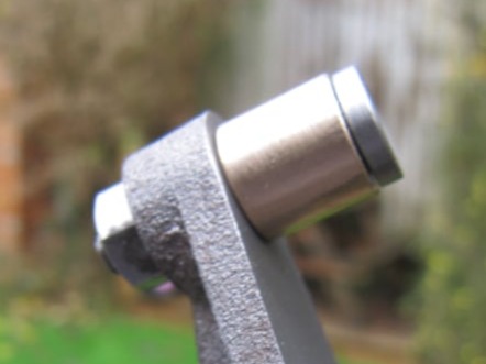
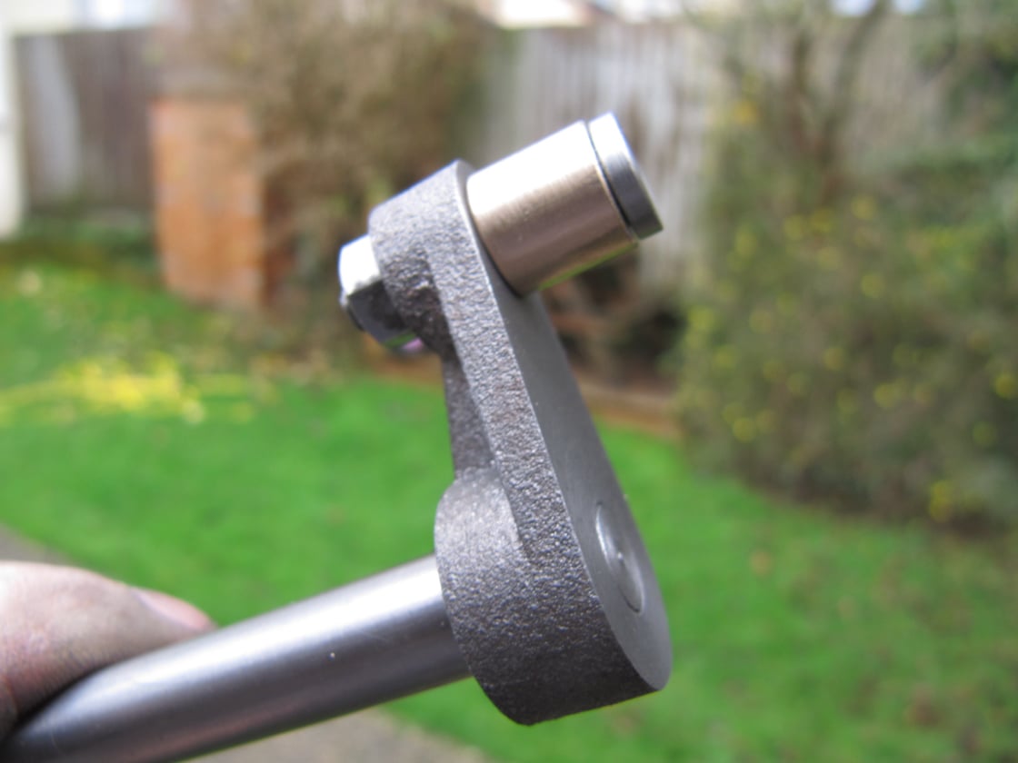
Like any crank web, the cast crank part was designed to hold two shafts at a given offset.
However the two holes would need to be parallel in all planes for it to work without imparting a twisting action into the system; and the holes should be the correct distance apart to match the piston stroke.

Mobirise Website Builder

The crank casting was held in the 3-jaw chuck and a square used to set it upright to the lathe bed.
In this setting the hole for the crank was drilled and reamed. Half the amount needed to get the part to final thickness was machined from the back face of the crank.

Mobirise Website Builder

The crank was set to run true in the 4-jaw chuck so that a concentric step could be machined to suit the hole just drilled in the crank web.
A collet chuck could also be used but one the correct size was not available. 

Mobirise Website Builder

The crank was pinned to the crankshaft and the outer face machined to bring the part to final thickness.
Also in this setting the small end was faced to final thickness using light cuts because of the intermittent cut.

Mobirise Website Builder

The small end of the crank was drilled on the drill press making sure the table was set as square as possible to the drill axis.
Absolute accuracy would not be needed because the hole would be used to hold a shouldered pin which should pull itself square to the machined faces. However the hole should still be drilled as carefully as possible.

Mobirise Website Builder

The crank pin was turned in one setting just using the 3-jaw chuck. The diameters and steps were turned using a sharp point tool to create nice crisp corners.

Mobirise Website Builder

The crank bush was turned to be a push fit in the connecting rod and was reamed to be a running fit on the pin.
The length of the bush was progressively reduced until it was a free running fit on the pin with the nut fully tightened up.

Drag and Drop Website Builder