Mobirise Website Builder

Stuart Victoria
The Connecting Rod

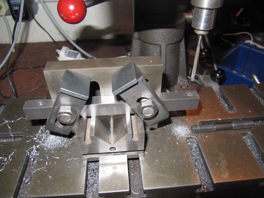
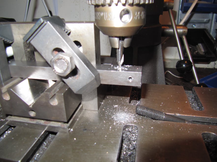
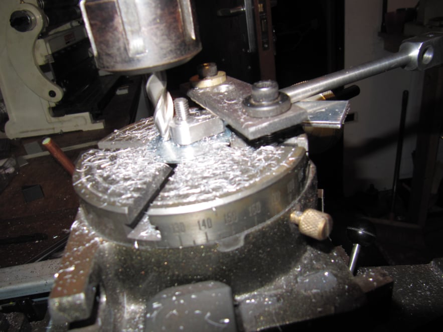
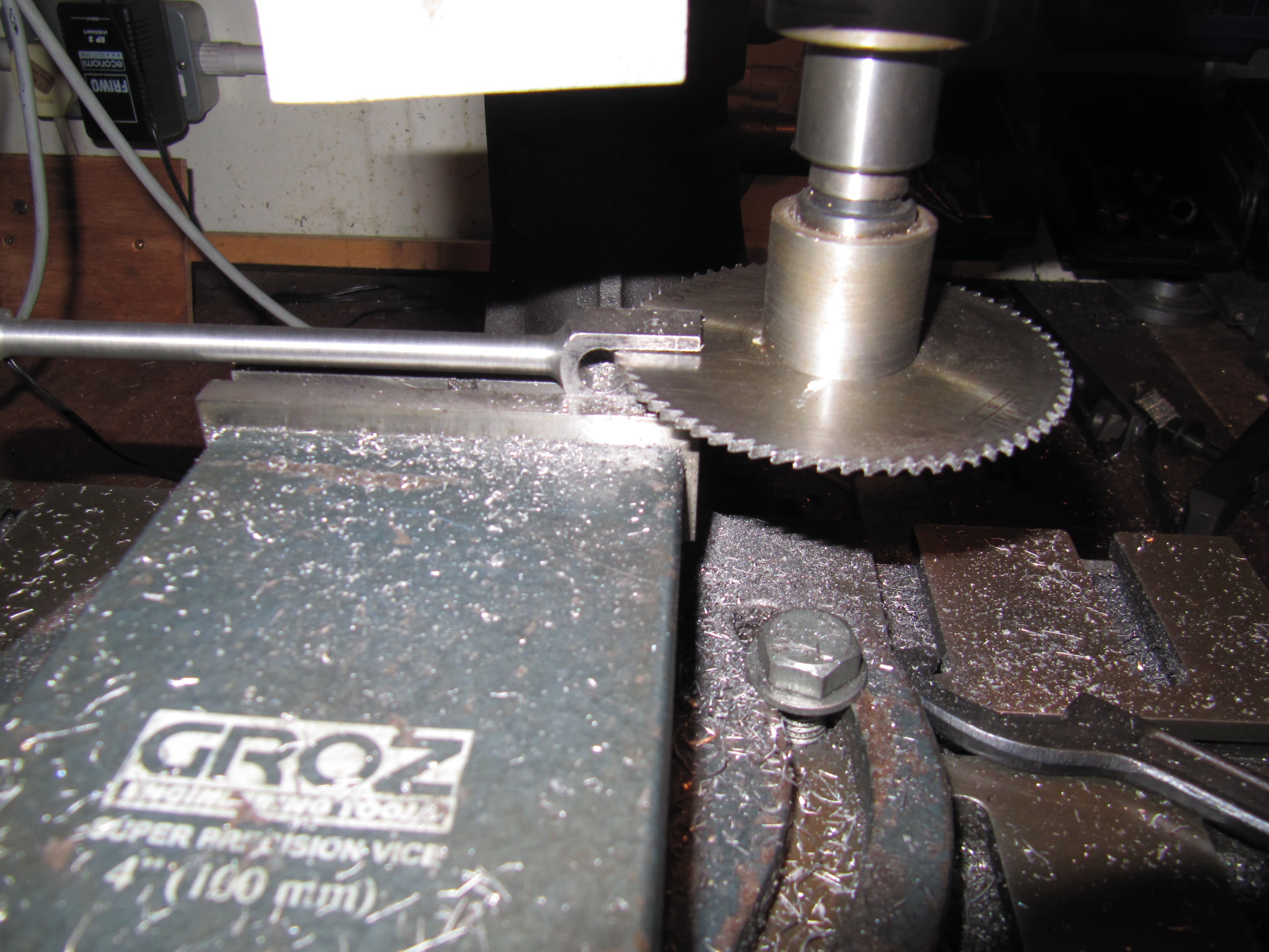
The connecting rod itself only has two critical parts and these are the pivot holes at each end. These features should be parallel in both planes and the correct distance apart for the engine to run smoothly.
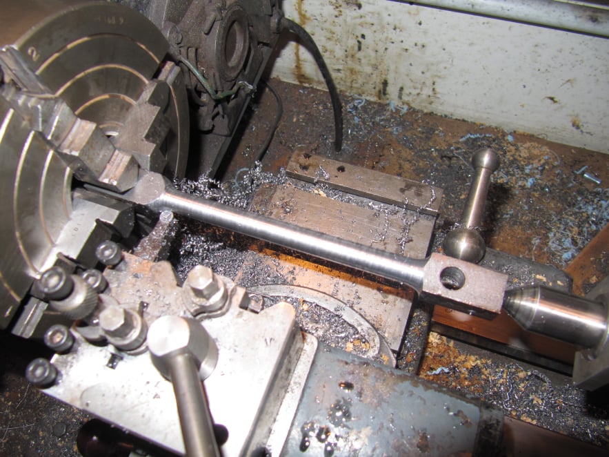
However to make the rod look good a significant amount of additional work is needed to turn the square stock into a round rod.

Mobirise Website Builder

The steel bar was set level on a vee block on the milling table and clamped to an angle plate. The part was set to be parallel to the table axis.
The centreline of the bar was found using a centre finder in the chuck.
In this orientation the two critical holes were drilled and reamed to final size using the mill DRO to get the spacing exactly correct.

Mobirise Website Builder

Then the bar was rotated 90° and a third hole was drilled for the curve on the inside of the forked end.

Mobirise Website Builder

The end of the connecting rod blank was located using the 4 jaw chuck and a DTI, then it was centre drilled so that it could be mounted between the 4 jaw chuck and the tail stock.
A profiling tool was used in the lathe to shape the main body of the rod. The plans called for a very slight convex profile, but to simplify the design, this connecting rod was just turned parallel.

Mobirise Website Builder

The crank end of the connecting rod was shaped on the rotary table,
The part was clamped with a single clamp bar and some packing to ensure it was horizontal.
A centre stud mounted in the rotary table made sure the cuts were taken concentric with the hole.
An alternative would be to use filing buttons if no rotary table is available.

Mobirise Website Builder

The fork in the other end of the rod was cut using a slitting saw in the mill. A slow speed and careful cuts were needed to remove the waste material.

Mobirise Website Builder

Three heat-treated filing buttons were used to help form the rounded ends to the fork.
The set up shown shows how the work was clamped without risk of distorting the part. A length of 1/8th dowel was used to align the filing buttons.

No Code Website Builder