Mobirise Website Builder

Stuart Victoria
The Steam Chest, Cover and Valve

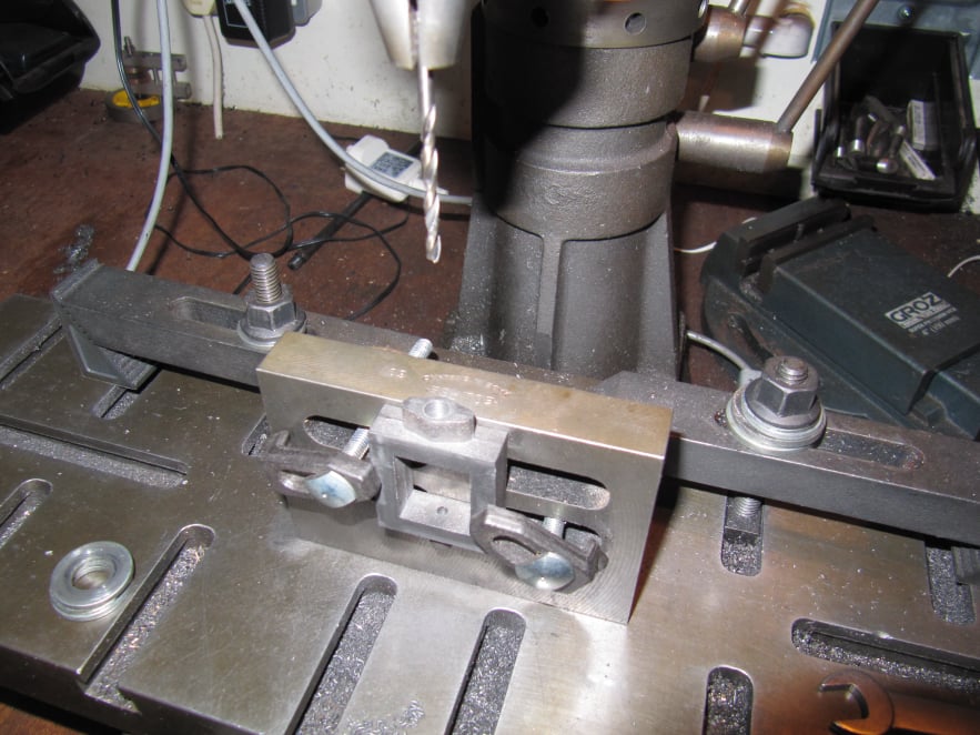
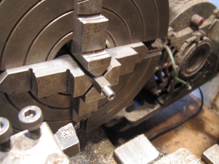
The steam chest and cover could be machined in the four jaw chuck or on the milling machine. The milling machine was chosen for the process described here.
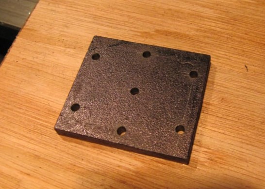
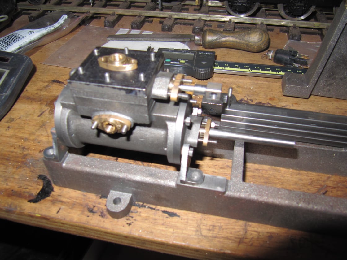
For this build the external faces of the steam chest were left rough cast.

Mobirise Website Builder

The steam chest was machined by clamping it firmly on the milling table and skimming the correct amount of each side.
The amount removed was different for each side to get the valve rod boss the correct position.
Actually it was only necessary to get the boss the correct distance from the cylinder face of the steam chest, the other face could be arbitrary.

Mobirise Website Builder

The steam chest was then mounted on an angle plate for the hole drilling.
It was set vertical by its outside edges and the centre of the boss was found using an edge finder.
A range of drills were used to centre-drill, drill, ream and counter bore the hole.

Mobirise Website Builder

The cover plate was already the right size to match the outside (unmachined) faces of the steam chest. So it was marked out for the mounting holes and steam inlet and drilled on the drill press.

Mobirise Website Builder

Next the steam chest and cover were clamped together and the plate holes were transfer drilled into the steam chest.

Mobirise Website Builder

The valve rod was mounted in a collet chuck in the lathe with the minimum of material extended from the chuck to minimise deflection.
The small diameter end section was machined in this setting using the lightest possible cuts and a sharp tool.
Then the valve rod was pulled out of the chuck to add the threaded section.
Finally the part was reversed in the collet to add a thread on the other end.

Mobirise Website Builder

The valve rod end was mounted centrally in the 4-jaw chuck and drilled and tapped to suit. the valve rod.
Then a round shoulder was added to the part before removing it from the chuck.
Finally the part was cross drilled on the drill press taking care to ensure the part was mounted square to the drill bit.

Mobirise Website Builder

The valve plate was not machined but was polished on its working face by rubbing the part of fine emery paper over a known flat surface such as a sheet of glass.

The adjuster nut was simply marked for a central hole which was drilled and tapped in the drill press.

AI Website Generator