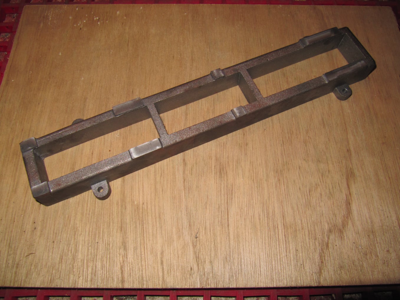
Mobirise Website Builder

Stuart Victoria
The Box Bed

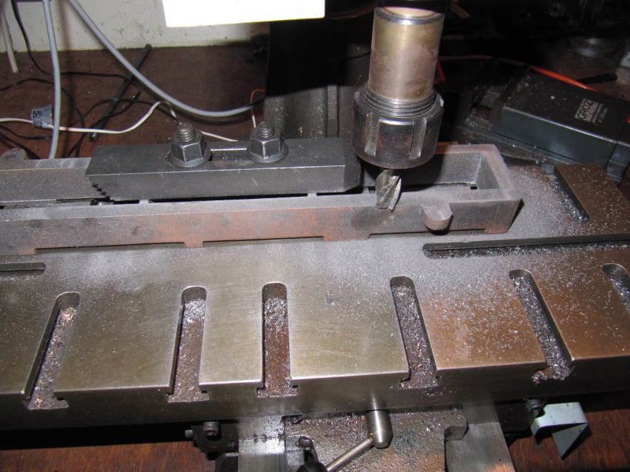
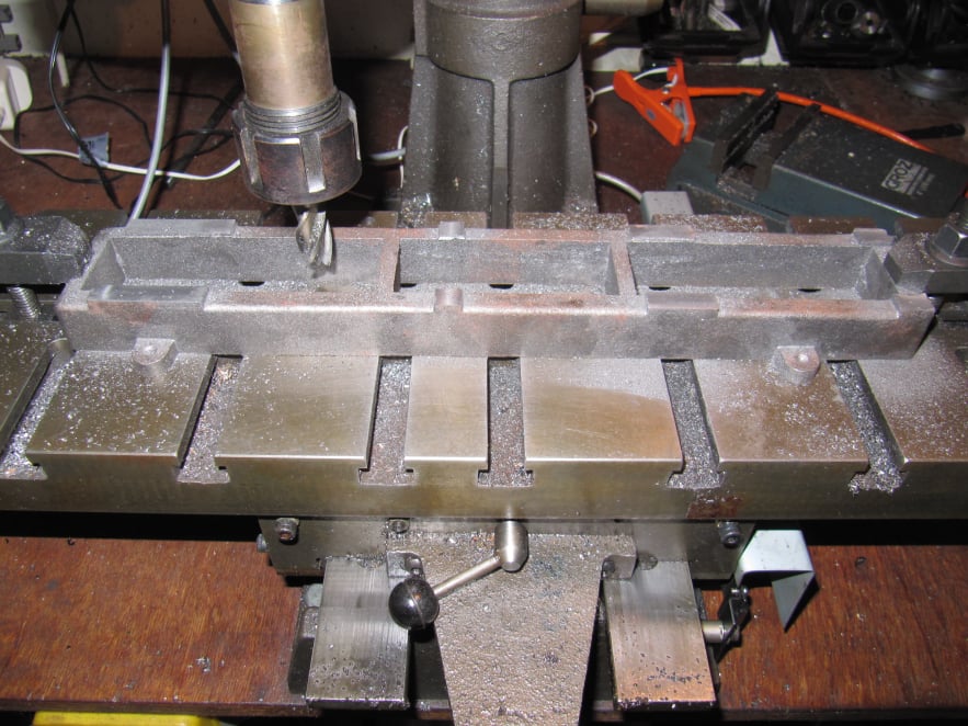
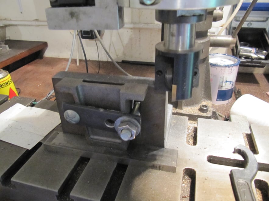
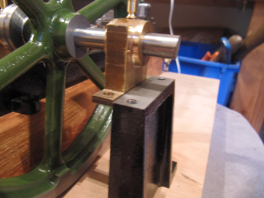
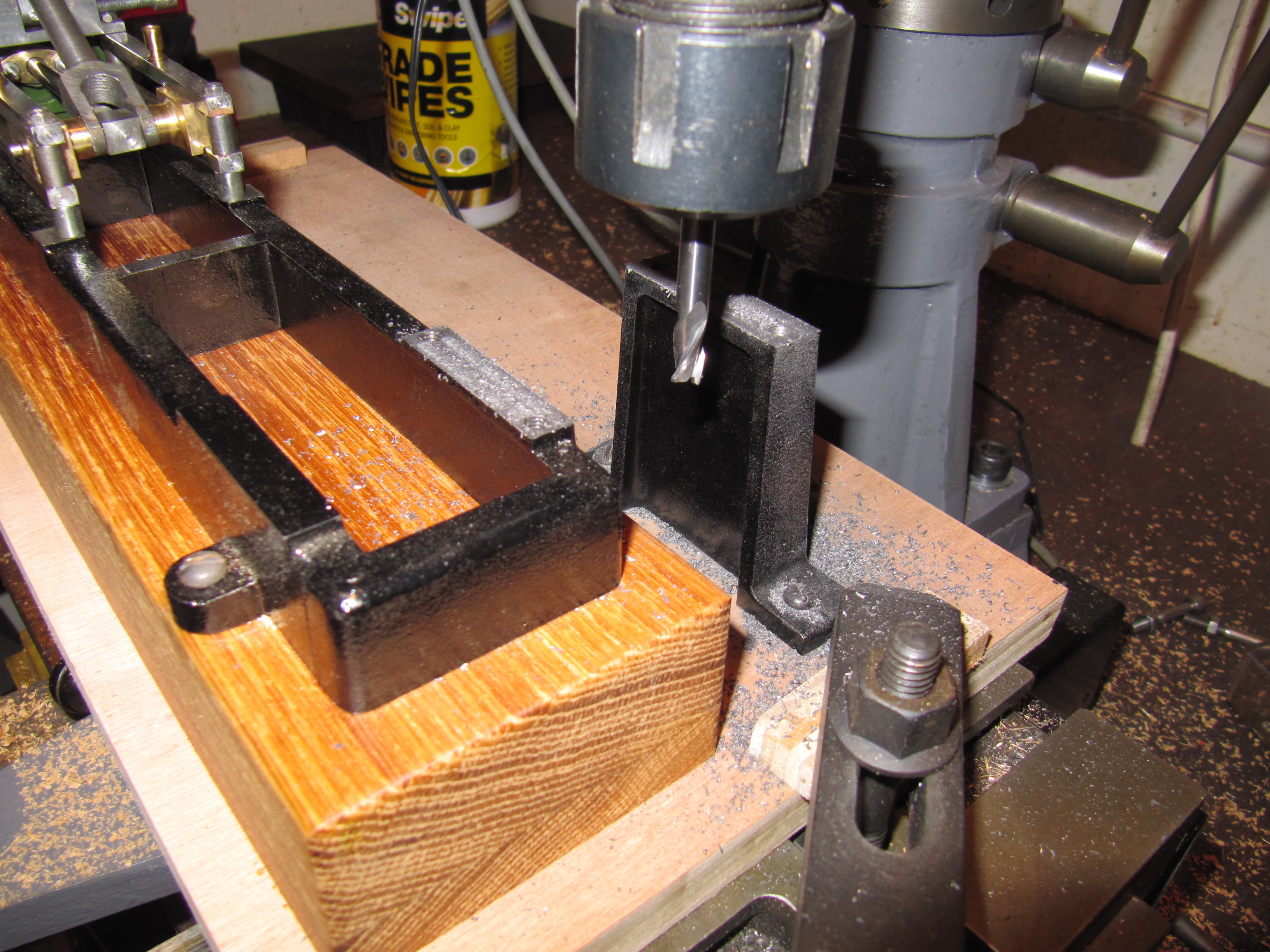
The box bed just required finishing of the top and bottom surfaces and the addition of the mounting holes.
The whole of the bottom was machined smooth so the engine could sit level but only the working surfaces were machined on the top face.
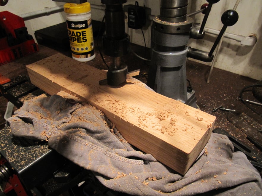
Overall thickness of the base was unimportant as long as the final size was taken into account when making the wooden base

Mobirise Website Builder

The bottom was machined first, but in two settings.

First the bed was clamped by the crossbars, so the whole outside edge could be machined. Then the clamps were moved to the outside edge so that the crossbars could be taken down to the same height.

Mobirise Website Builder

The top working areas were reduced down to the same height throughout.
All the mounting holes for the engine parts were drilled once the rest of the engine had been made (details on the assembly page). This would ensure that parts would fit with the required clearances and sit in line with the boxbed.
Just drilling separate parts onto the base would not allow for any tolerance build up.

Mobirise Website Builder

The bearing support was machined using one of the side faces as a reference. This would result in a part that was vertical on one face and sloped on the other.
The part was mounted against an angle plate on the mill to machine reference surfaces on the feet.

Mobirise Website Builder

The the part was turned the other way up to machine the top face so that top and bottom would be parallel.
Once the bearing mounting holes had been established in the bearing blocks, the same spacing was drilled through into the top of the bearing support.
To finish; two mounting holes were drilled in the centre of each foot.

Mobirise Website Builder

The wooden base was made to a height that would be the difference between the box bed height and the bearing support height. In this model the difference was 46.46mm.
A piece of Oak was sawn and sanded to be just oversize.
Then the underside of the block was skimmed using a fly cutter in the mill to ensure the top face would be level.

Image of bearing/support block clash

Next the bock was mounted on the base and and engine and bearing support screwed into position.
It was then possible to view any clash between the outer bearing and the support block.

Image of bearing/support block clash

The milling machine was used to machine both bearing mounting surfaces to the same height.
Light cuts and a small sharp cutter were used to avoid high cutter loads which could move the tall support block on the base.

AI Website Generator