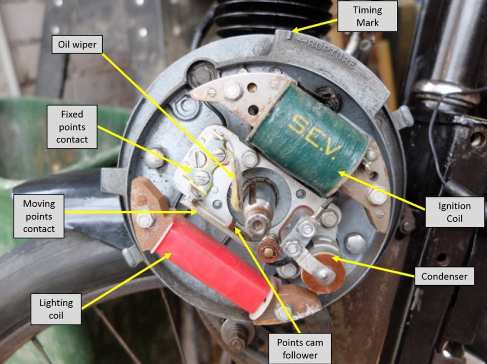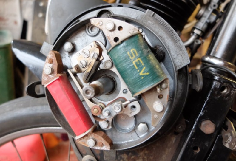
The points (contact breakers) on the Velosolex are housed behind the flywheel and as the motor is a 2-stroke, the plug sparks on each revolution of the crank.
The spark has to be timed to get the engine to run correctly and a procedure is given here.
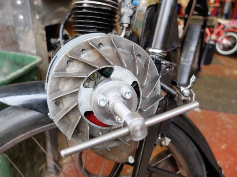
Most of the difficultly in working on the points is accessing the area behind the flywheel. The flywheel has some holes which enables some access but to replace the points the flywheel must be removed.
Note: The three M6x1mm screw holes should be used to extract the flywheel from the crankshaft, rather than any other levers or pullers as the flywheel is easily damaged.
A homemade flywheel puller is shown here and the dimensions are given in the drawing.
Before using the extractor the centre nut should be undone using a 21mm socket or spanner.
With the flywheel removed the magneto components are exposed.
To replace the points, both the fixed contact plate and the moving arm should be removed.
It is easier to remove the fixed plate first so that there is less tension on the spring when removing the other parts.
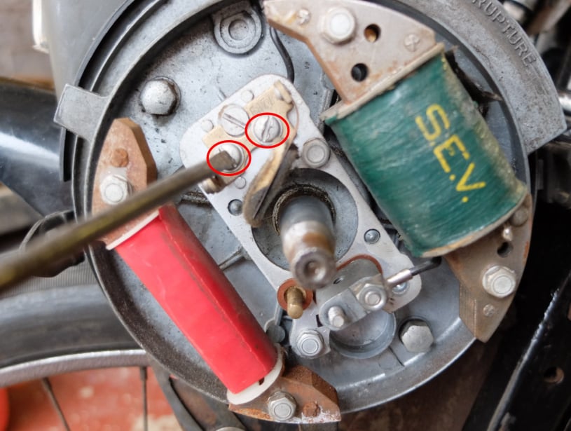
Remove the fixed plate by undoing the two fixing screws shown.
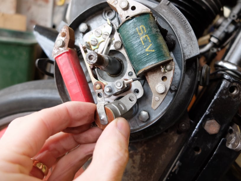
With the fixed contact plate out of the way the condenser should be removed to allow access to the securing screw for the moving arm of the points.
A 7mm spanner or socket should be used to undo the two retaining nuts.
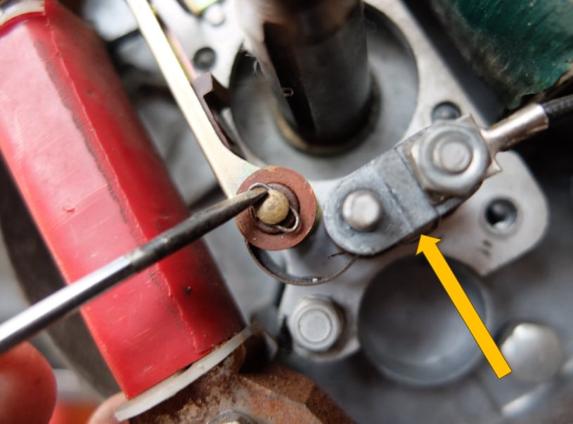
The moving arm of the points can be removed by undoing the spring securing screw (arrowed) and easing off the wire spring clip on the point pivot arm.
Reassembly is the same process in reverse.
The oil wiper pad should be lightly oiled as this will reduce wear on the points cam follower when the engine is running.
Every time the points are replaced it is necessary to set the engine timing. This is done by replacing the flywheel cover and then moving the engine by hand using an indicator to work out when the points open and close.
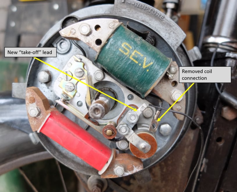
To set the timing the ignition coil should be disconnected from the circuit and a "flying lead" made up and attached to the same contact point as shown here.
The flywheel should be replaced ensuring that the key way inside the flywheel aligns with the slot in the crankshaft.
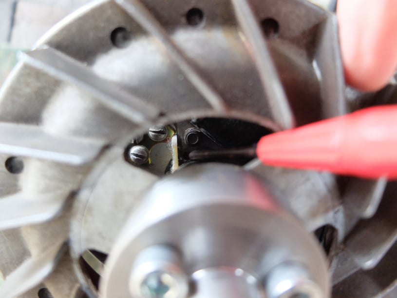
Also be sure to left the felt wiper pad clear with a screw driver as the flywheel is pushed into place (see photo).
There is no need to secure the flywheel with the centre nut for the timing setting process.
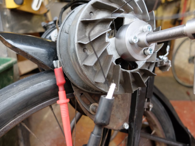
The new "flying lead" should be pulled through one of the holes in the flywheel and then be connected to one side of a multimeter. The other multimeter connection should be earth on the engine housing.
The multimeter should be set to check continuity with either a "beep" tester or resistance setting.
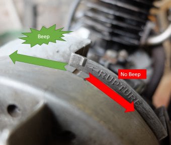
For the engine to run, the points should open just as the "rupture" mark is aligned with a notch on the flywheel. The points opening will be indicated by the continuity Beep stopping or by a resistance measurement going to maximum (infinite).
It is worth removing the spark plug to make this motion easier. By oscillating the flywheel about this mark it should be possible to see if the timing is correct or not.
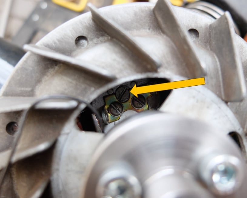
If the points don't open at the "Rupture" mark then the two clamp screws for the fixed point contact should be loosened and the cam screw (arrowed) turned to increase or decrease the points gap.
Through trial and error, it should be possible to find a position where the points open with the alignment of the flywheel marks.
Easiest Website Builder