Mobirise Website Builder

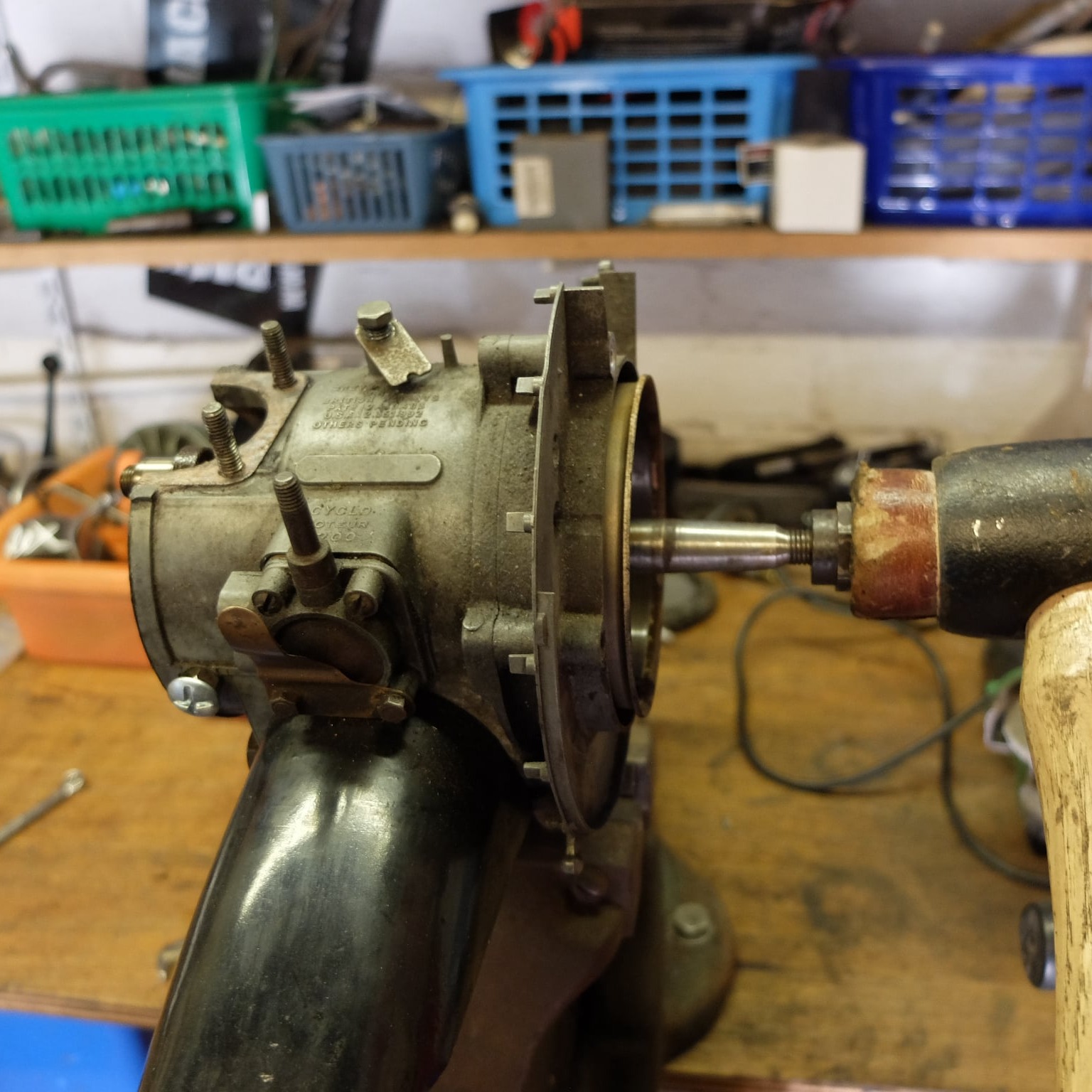
Rebuilding the Velosolex 3300 Motor Unit

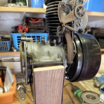
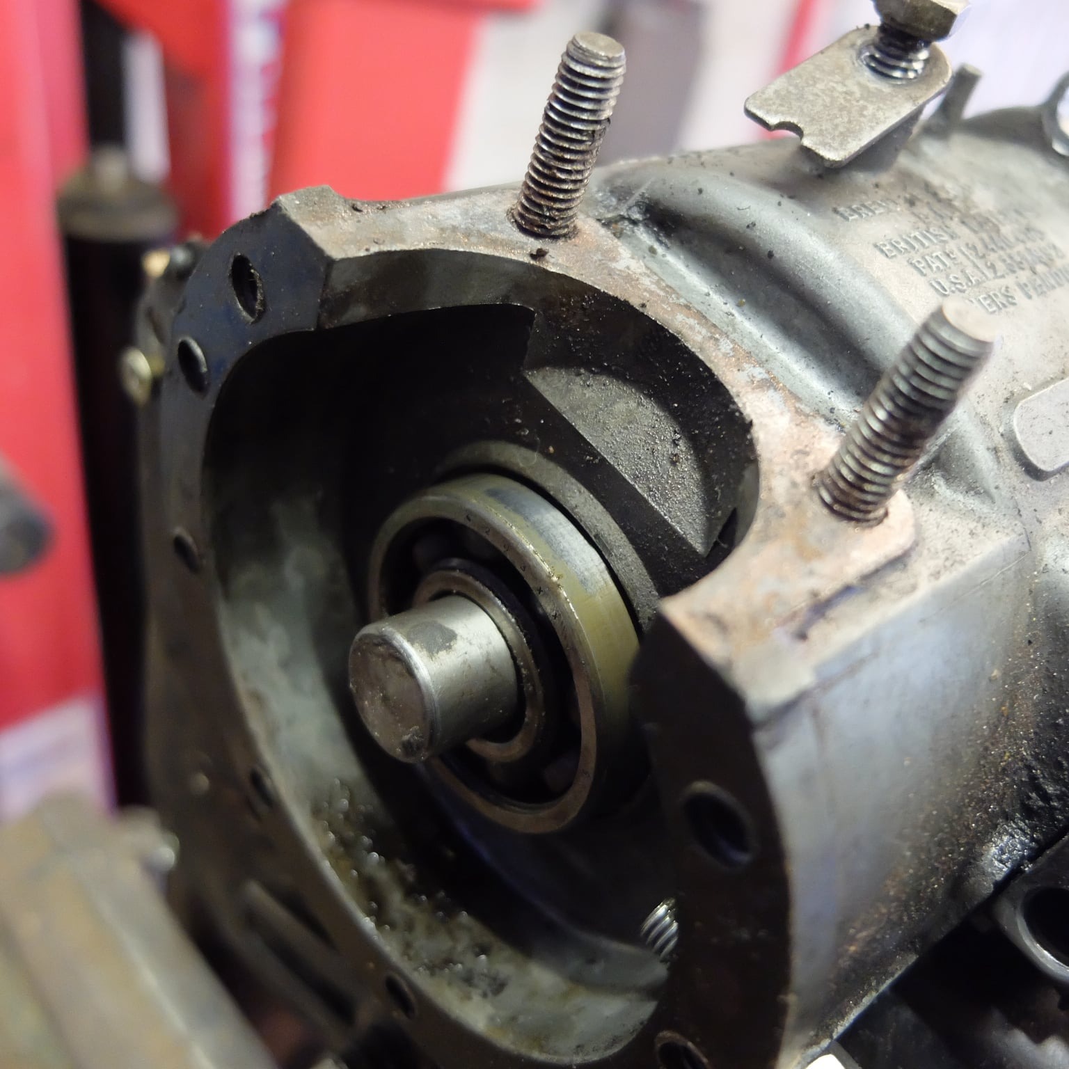
This article shows the steps needed to tear down and rebuild the VeloSoleX 3300 engine assembly.
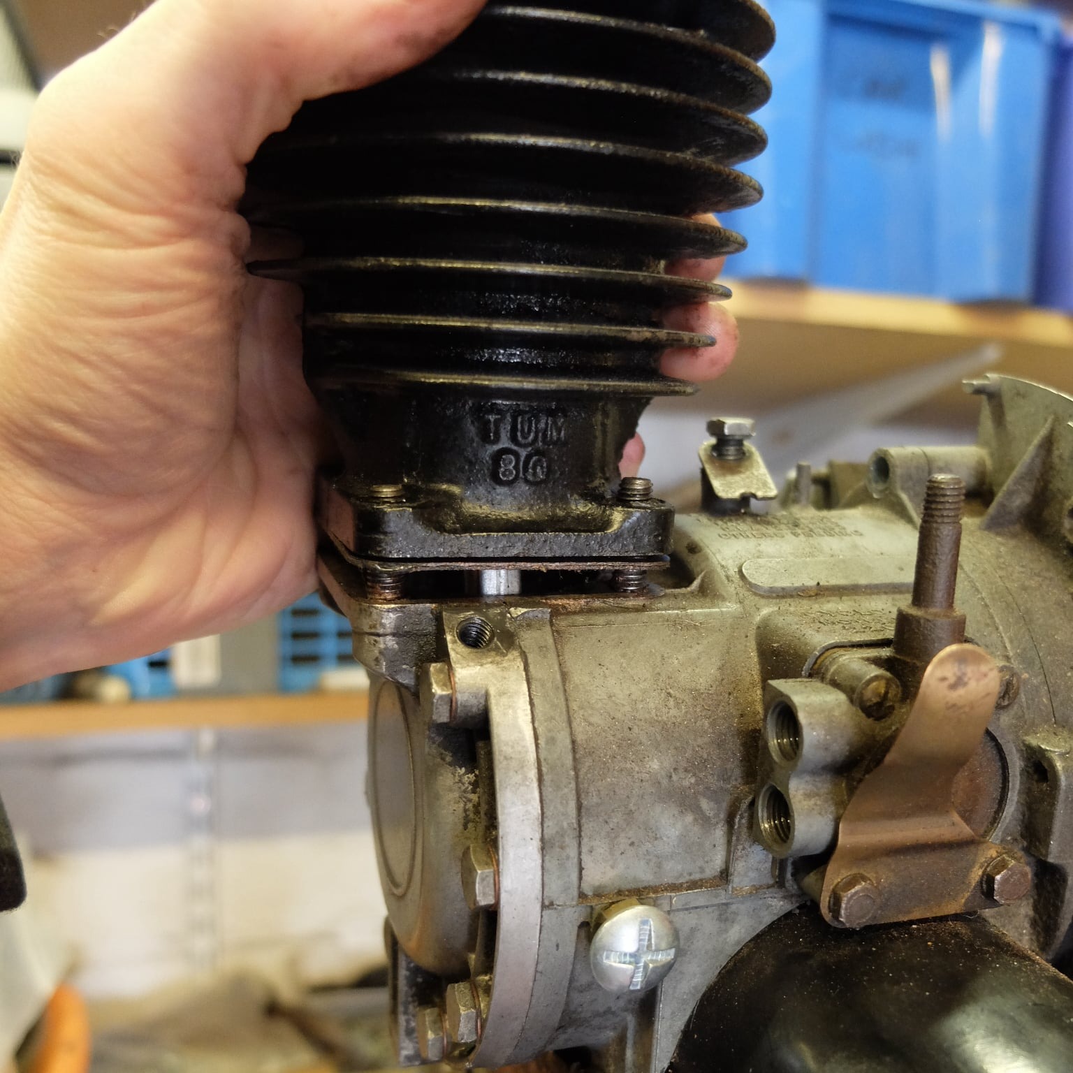
The 3300 engine was only produced for a few years (between 1962 and 1965), because it was a transition model between the 2200 and the 3800.
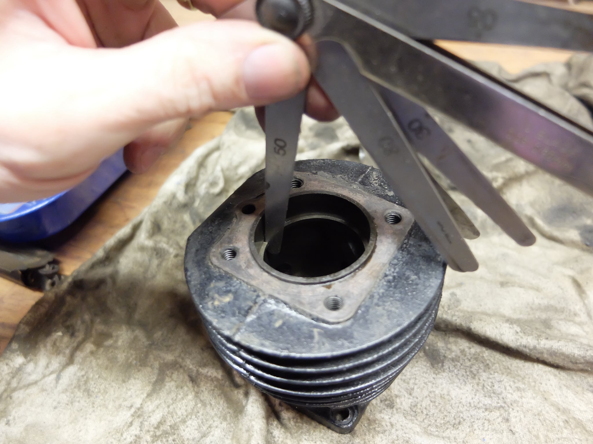
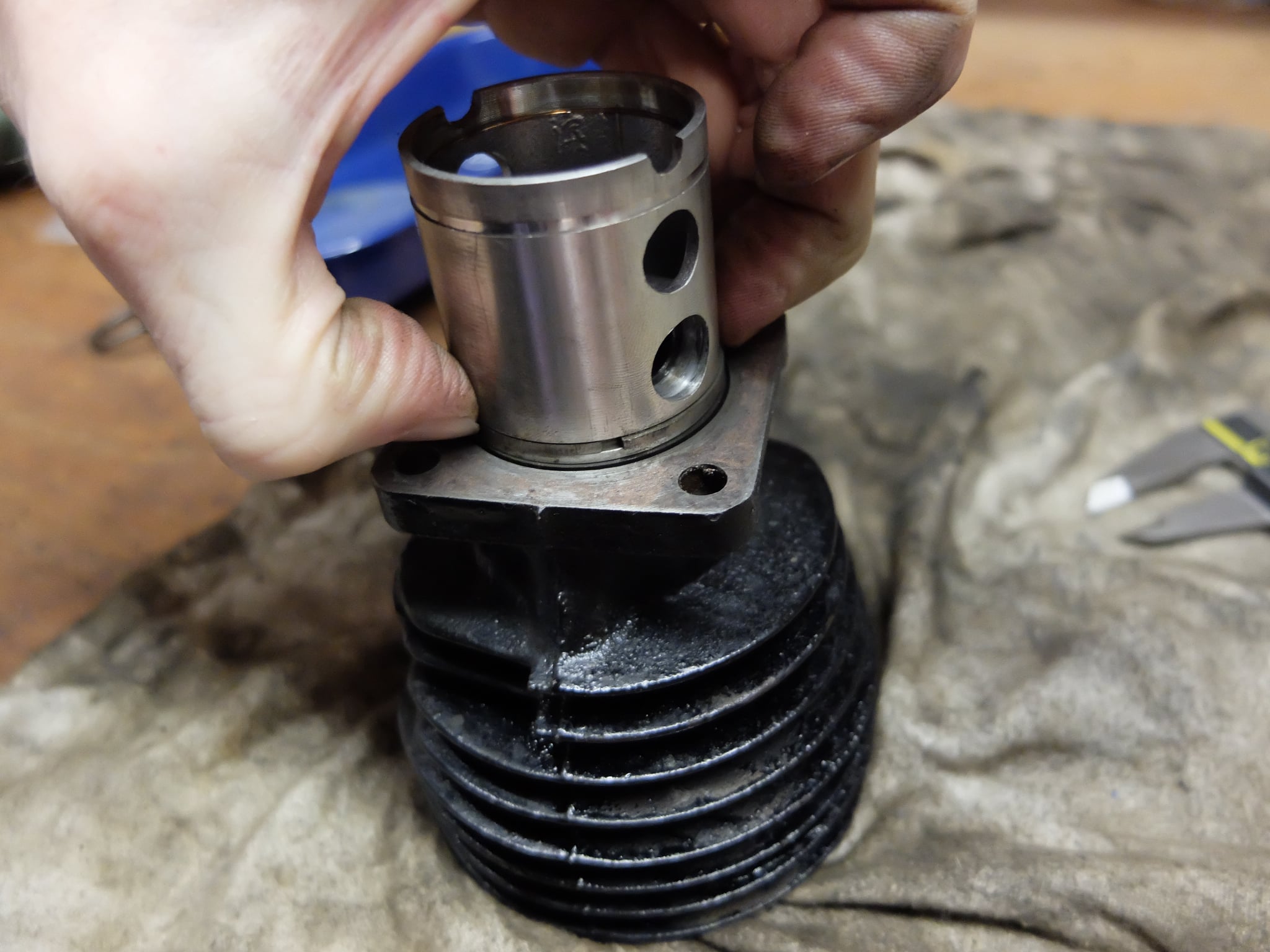
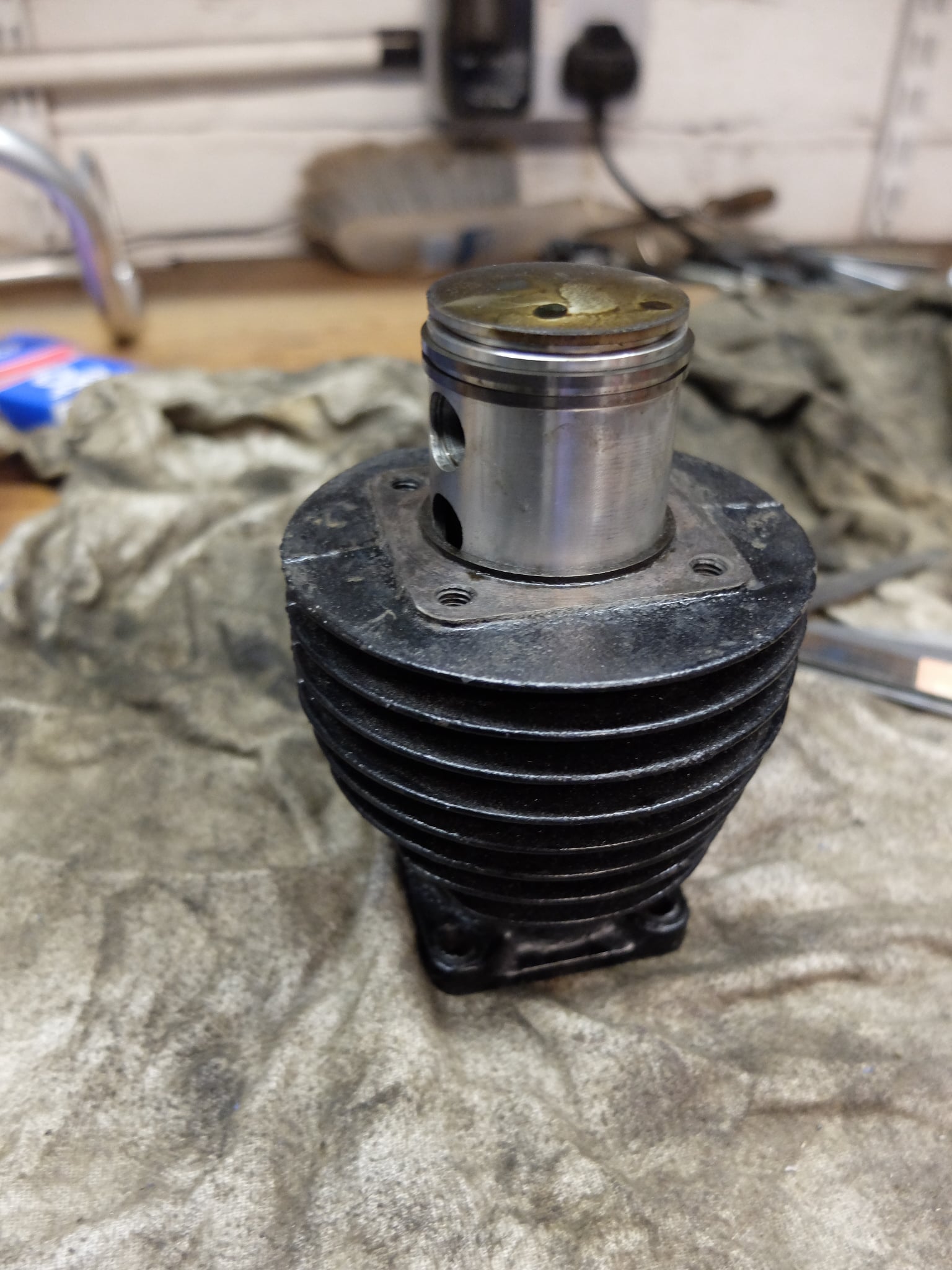
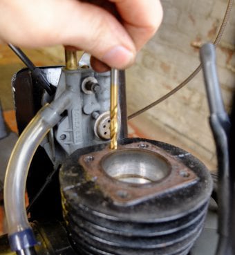
For this reason the bottom of the engine is the same as the older 2200 model and the cylinder and fuel system the same as the later 3800 machine.

Disassembly

Mobirise Website Builder

The engine should be removed from the bicycle and screwed to a piece of hard wood cut to fit between the mounting plates. The wood can be  clamped in the vice and the motor held to the wood with 4 short self-tapping screws. 

Mobirise Website Builder

The crank can be locked in place by inserting a longer M6 screw into the plugged hole at the front of the engine.

Mobirise Website Builder

With the flywheel cover removed, the centre 21mm nut is undone, with a plug spanner if nothing else is available.

Mobirise Website Builder

With the nut removed a flywheel puller can be used to pull the flywheel off the crankshaft.

Mobirise Website Builder

To remove the stator plate this bolt needs to be removed.......

Mobirise Website Builder

....... along with these two, all with a 9mm spanner.

Mobirise Website Builder

Some sort of stator puller must be used to extract the stator plate by applying the force to the ends of the coils rather than bending the plate itself.

Mobirise Website Builder

Behind the stator plate is the clutch. The nut on the clutch can be very tight and a box spanner or the plug spanner) can be used to undo it.

Mobirise Website Builder

With the nut a spring washer removed the clutch mechanism can be extracted by pulling it apart as shown and withdrawing it from the clutch housing.

Mobirise Website Builder

Be sure to retain the spacer washer behind the clutch mechanism.
At this point there is a special tool to extract the drive roller assembly and clutch housing along with the surrounding mounting plate.
However these parts can also be drifted out from the other side.

Mobirise Website Builder

To remove the crank case cover, first the cylinder must be removed.
The 4 cylinder head bolts can be undone with a 9mm spanner, but they can be left in place.

Mobirise Website Builder

The cylinder head complete with decompressor valve, bolts, spacers, washers and the engine lever can now be removed.

Mobirise Website Builder

The clear overflow pipe from the carburetor can be pulled off and the three 9mm tank securing bolts undone.

Mobirise Website Builder

The fuel outlet to the pump, at the bottom of the tank, should be removed with the 9mm wrench.

Mobirise Website Builder

The carburetor and inlet manifold can be removed by undoing the fuel pipe at the bottom and the two inlet manifold bolts.

Mobirise Website Builder

The two fuel lines can be unscrewed from the pump using a 9mm spanner.

Mobirise Website Builder

The 4x 9mm nuts at the base of the cylinder can be removed and the cylinder lifted clear with the base gasket.

Mobirise Website Builder

To extract the piston and gudgeon pin, remove the circlip on one end and slide out the pin.

Mobirise Website Builder

The crank end cover plate can be released by undoing the eight 9mm bolts.
Note the top screws are longer.

Mobirise Website Builder

The connecting rod can now be removed by undoing the big-end nut with a 14mm spanner.

Mobirise Website Builder

The crank can now be tapped out gently from the flywheel end. The flywheel nut can be used to protect the thread on the crank and only a soft mallet should be used.

Mobirise Website Builder

Extracting the crank.

Mobirise Website Builder

Take a note of any shims being the crank.

Mobirise Website Builder

The drive roller can be removed with the mounting plate and clutch housing.
There are a number of spacers and sleeves in and around this assembly which should be kept in the correct order.

Mobirise Website Builder

The crank bearing can be drifted out from the flywheel end using a suitable shouldered rod or threaded rod with a nut and washer.
There should be another shim on the other side of it.

Mobirise Website Builder

The crank bearing can be drifted out from the flywheel end using a suitable shouldered rod or threaded rod with a nut and washer.
There should be another shim on the other side of it.

Mobirise Website Builder

Parts

As a minimum, a gasket set will be needed to reassemble the engine; furthermore there are two bearings in the lower half of the engine. In particular the crank bearing must be sealed well, to allow the vacuum in the engine sump to operate the fuel pump and also transfer fuel to the cylinder.

Replacement bearings are
Crank bearing
6203 2RS** 40mm OD x 17mm ID x 12mm Thick.
Stator Bearing
6202 2RS** 35mm OD x 15mm ID x 11mm Thick
**2RS = 2 rubber seals
Branded, double rubber sealed bearings are best.
For top end work then a new spark plug, new decompresser valve are a good idea
Replacing the fuel and air filters is also good practice.

Reassembly

Mobirise Website Builder

Rebuild is the reverse of disassembly with the following notes.
The new crank bearing should be replaced with the original shims.

Mobirise Website Builder

Ensure all spacers and collars are reassembled including the drive roller sleeve (above).....

Mobirise Website Builder

....and the washer behind the clutch mechanism.

Mobirise Website Builder

The crank cover gasket should be lightly oiled to stick it in place on the engine housing.

Mobirise Website Builder

The crank cover should be located but not tightened until the cylinder has been replaced. This is necessary to ensure the cylinder has a flat surface to bolt to.

Mobirise Website Builder

If the piston was removed the ring gap can be checked and should be between 0.15mm to 0.3mm. Each ring should be placed in the bore and squared up using the piston skirt as a guide.
Then the gap can be checked with feeler gauges.

Mobirise Website Builder

To reinsert the piston in the cylinder it should be inserted from the bottom with each piston ring compressed in turn with the fingers. The cylinder bore has a taper on the bottom to aid insertion.

Mobirise Website Builder

If the piston and cylinder are measured the nominal dimensions should be:
Piston diameter : 39.35mm
Cylinder Bore : 39.50mm
If non-original parts have been  fitted then the difference between the piston diameter and the cylinder must be a maximum of 0.15mm.

Mobirise Website Builder

To decoke the decompressor channel, a 5mm drill can be wound into the vertical channel in the cylinder by hand.

Mobirise Website Builder

Likewise, a 3.5mm drill can be used to clear the angled channel in the cylinder head.
To reassemble the decompressor valve, screw the housing all the way in, and then back it off 1.5 turns.

Mobirise Website Builder

The cylinder head should be assembled with a new gasket and tightened to 105 pound inches of torque. A spanner and spring balance can be used to set this if a torque wrench is not available. This torque should be re-done when the engine is warm.

Mobirise Website Builder

The stator bearing should be pushed into the stator plate before pushing the whole assembly onto the crankshaft.

Mobirise Website Builder

The clutch should be installed with the little + signs facing outward, otherwise the clutch will work in reverse.
The clutch nut should be done up tight - 284inlbs torque.

Mobirise Website Builder

The stator plate needs to be pushed into position by pulling against the crank. Just pressing the stator plate alone, may may move the crank out of its own bearing.
The flywheel nut can be used to do this, if combined with two lengths of 15mm tube.

Mobirise Website Builder

The stator needs to be  correctly orientated using the fixing bolts done up were used finger tight.

The short, then long, bits of tube can then be used with the flywheel nut, to push the plate fully home.

No Code Website Builder