Mobirise Website Builder

Making Sidecar Attachment Links

Early BMWs were 'sidecar ready.' They had mounting bosses and a significantly strong enough frame to take sidecar loads.

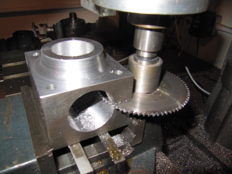
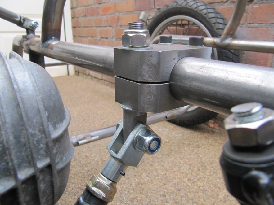
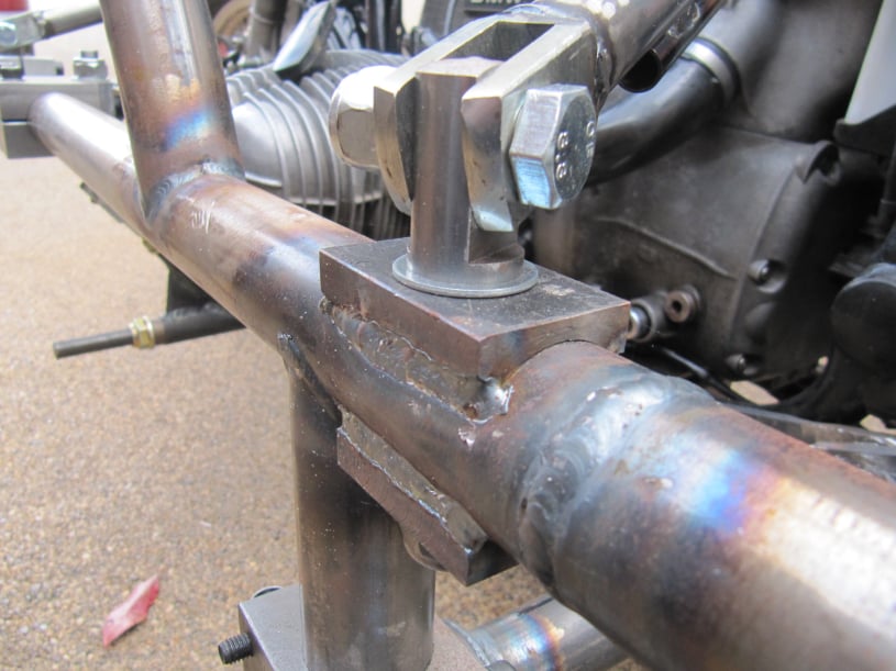
However the later /5, /6, and /7 series bikes had a frame made from lighter tubing and so careful clamp design would be needed to keep the frame from damage.

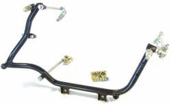
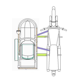
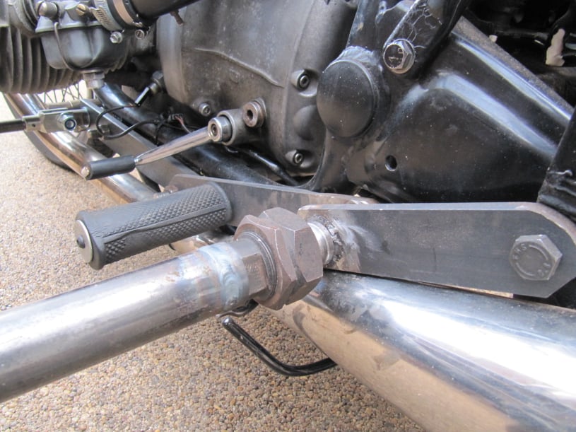
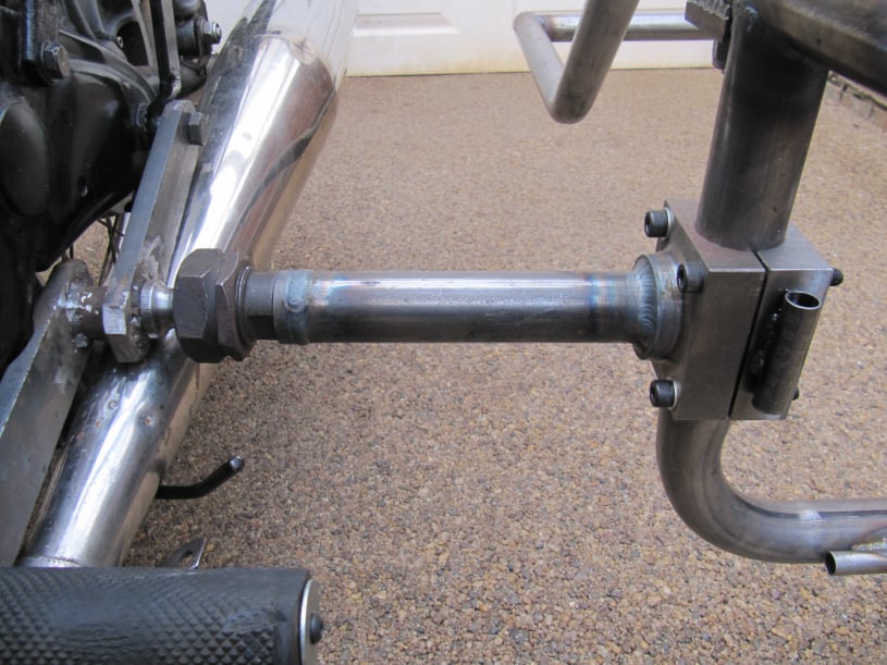
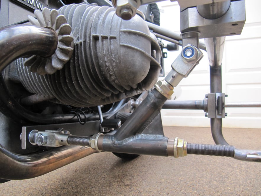
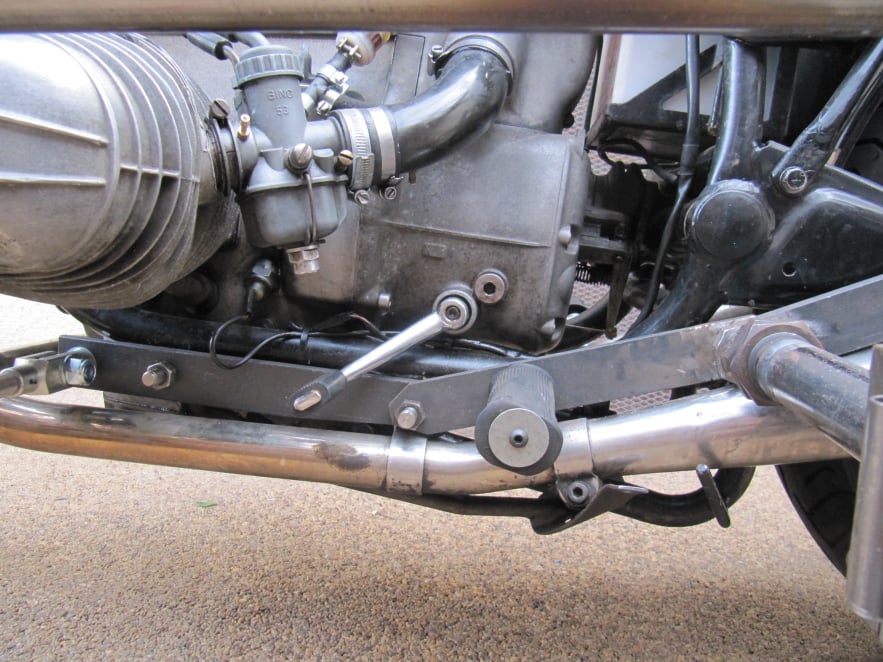
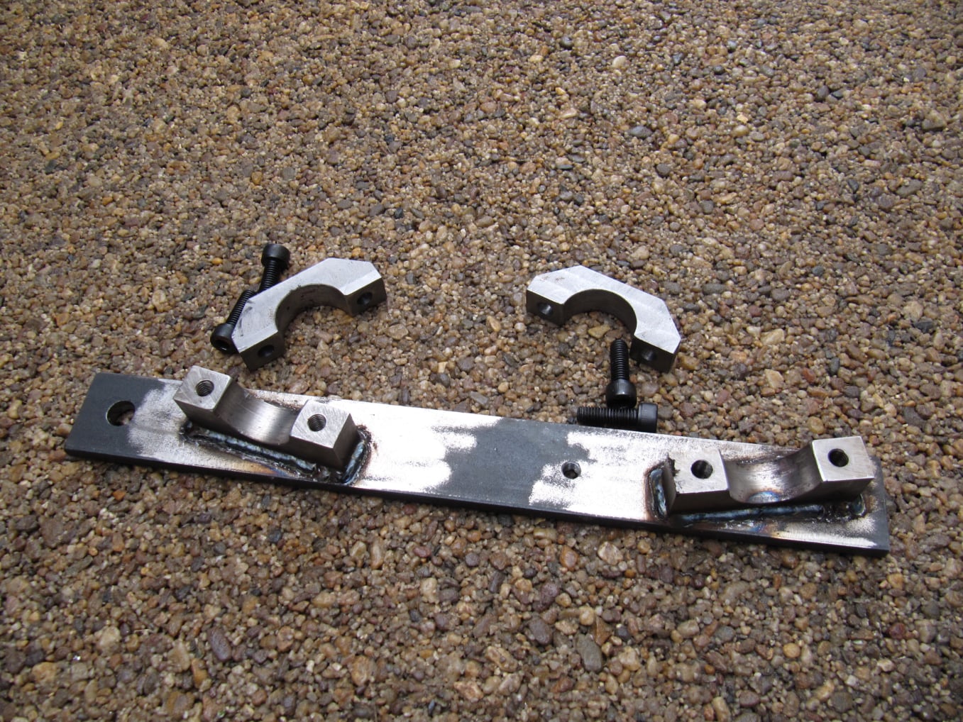
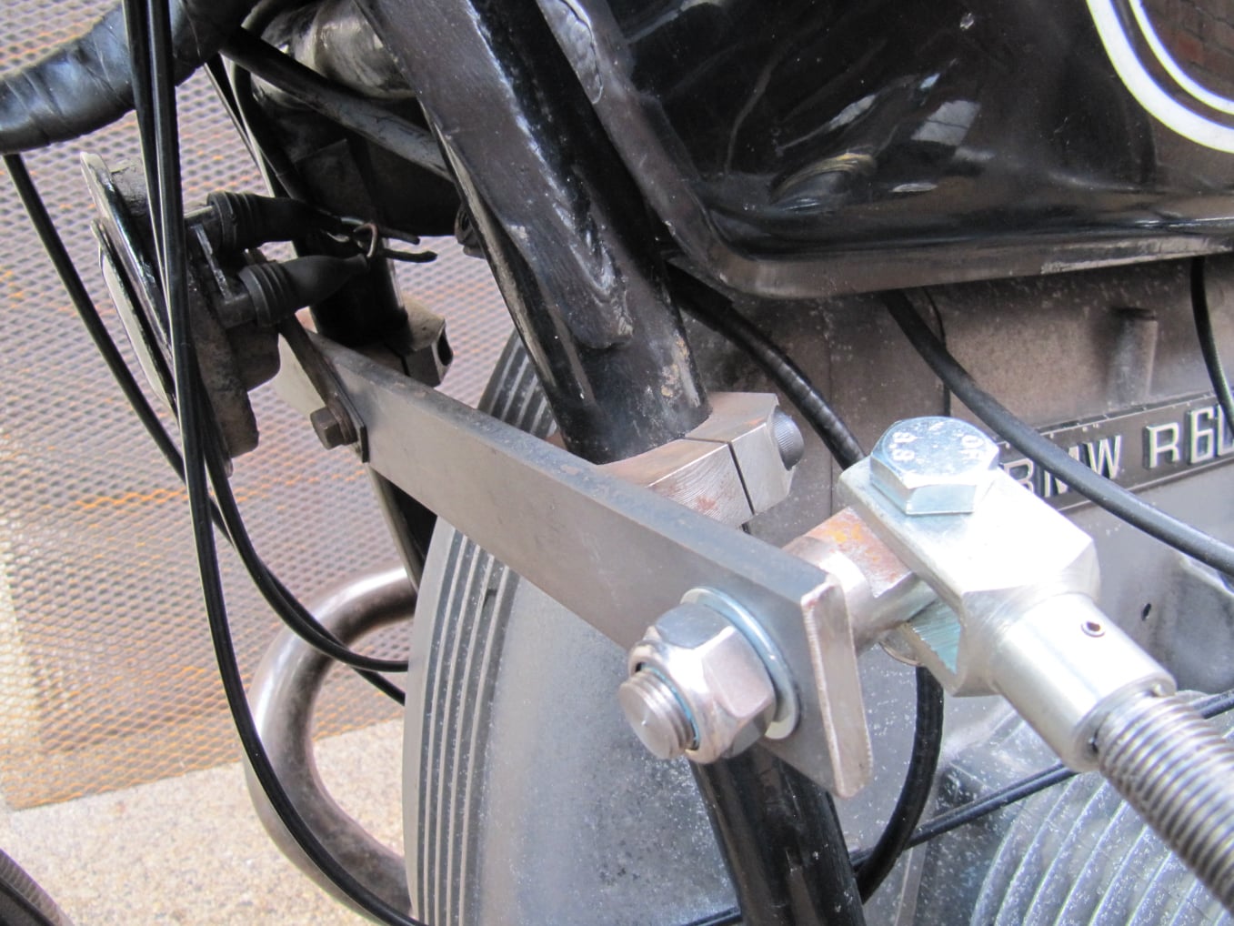
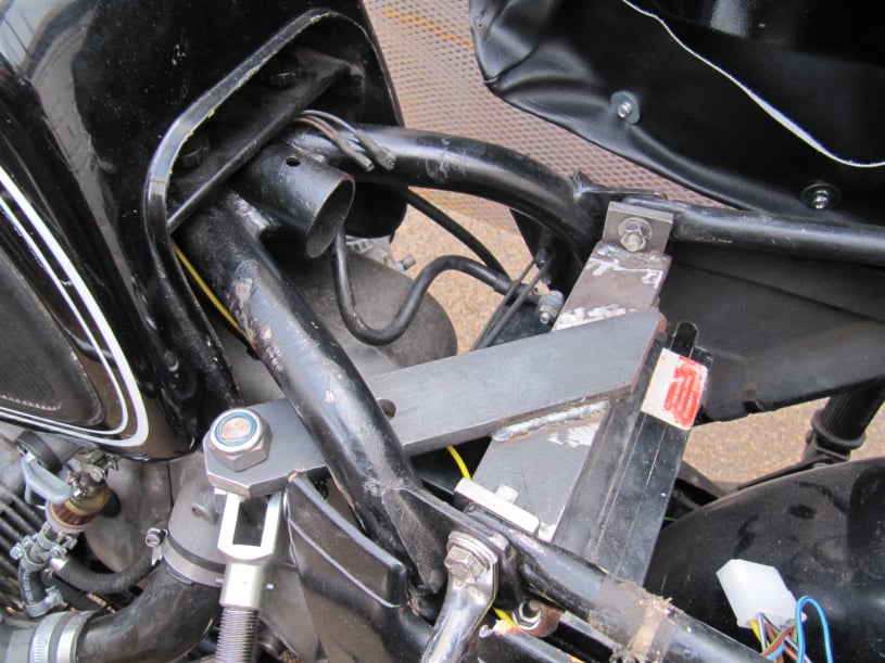
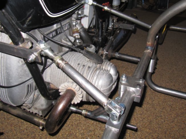
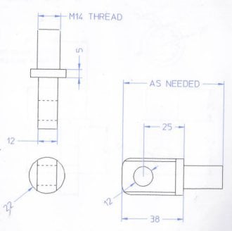
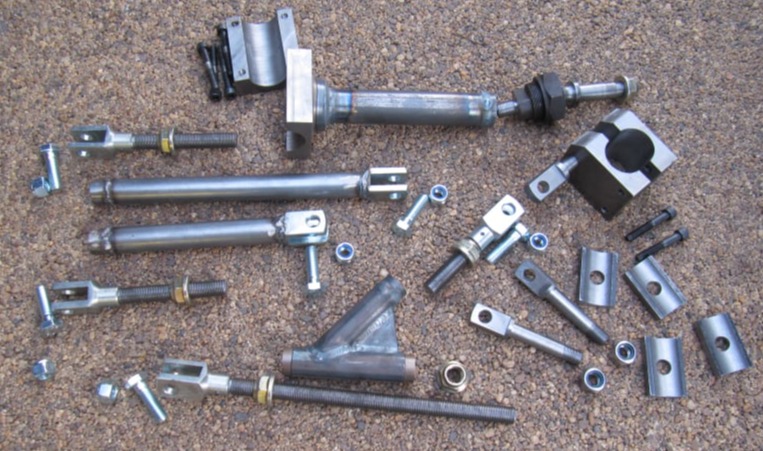
This page details the fittings and frame mounting points used for this project.

Mobirise Website Builder

Motorcycle Subframes

Airhead BMWs are frequently fitted with a separate subframe bolted to the motorcycle to help take the load from the sidecar. This is reasonably straight forward when the sidecar is mounted on the right hand side, but in the U.K. left hand hand sided mounting is required. The location and movement required of the gear lever makes sub-frame design more difficult. Not impossible, but tricky.

Instead it was decided to provide each mounting with some cross bracing to both sides of the motorcycle frame. This would ensure that the frame did not get damaged.

Mobirise Website Builder

The plan was to use a 4 point mounting system, fairly typical for a medium sized motorcycle with a light sidecar.
The lower rear mounting point would be a ball joint allowing angle adjustment in both the horizontal and vertical planes. This would enable Toe-in and Lean-out to be adjusted.
The lower front mounting would be designed to have a horizontal adjustment so that Toe-in could be adjusted without affecting lean or sidecar height.
The top two mountings would be standard adjustable struts to complete the set up.
This top view of a typical 4 point mounting system illustrates an important point.
The lower mountings are shown in green and the upper ones in Purple.
The lower joints can be parallel. This is OK and makes adjusting the bike easier.
However the upper links should be at an angle. This triangulation helps the sidecar and bike stay rigid without relying on the friction of clamps to keep everything in place.

Lower rear mounting

Mobirise Website Builder

The lower rear mounting used a second hand ball joint from EBay. This was a sidecar specific part from an old bike. It was lockable which would help hold everything rigid once angles had been set.
The mounting was attached to the passenger foot peg at the back and the rear engine bolt at the front. The material used was 10mm thick steel flat and the offset between these two strip parts was accommodated by adding a steel tube which also took the shank of the ball joint.

Mobirise Website Builder

The sidecar lower joint was a large thick walled tube welded into a split clamp. The end of this tube housed the other half of the ball joint.

The clamp was machined from a block of steel, bored to suit the sidecar frame diameter and then sliced to make a two part clamp.

Mobirise Website Builder

The frame clamp would be able to slide and pivot on the sidecar frame. This would enable sidecar wheel lead to be varied and also the sidecar height to be set to ensure the chair was level.

The ball joint on the bike side would allow the bike tilt and toe-in to be set.

Lower front mounting

Mobirise Website Builder

The lower front mounting was designed to be length adjustable so the toe-in could be set; and height adjustable so that the sidecar could be leveled.
A Y-shaped part was made from 25mm thick walled steel tube. This was braced and welded into a rigid assembly.
This design allowed the link to clear the cylinder head and also gave a nice horizontal adjustment facility.
The threaded rod was a fine pitched 16mm metric thread.

Mobirise Website Builder

The lower front mounting on the motorcycle was made from 10mm thick steel flat. It was bolted to the engine mounting bolts thereby using the engine to share the load across both sides of the frame.
The rear engine bolt which was longer was swapped to the front to accommodate the mounting plate; and a longer bolt was made up for the rear mounting.
The eye bolt for the front mounting was positioned with the clevis bolt horizontal so that this could be used as a pivot to adjust bike lean.

Mobirise Website Builder

Where the front mounting clamped to the sidecar frame a simple steel clamp was used. This was bored and sliced in the same way to the rear clamp part. The two clamp halves were joined with some cap head screws and a homemade eye bolt.

The clamp was able to slide on the sidecar frame and also pivot on the eye bolt giving enough degrees of freedom for adjustment of toe-in.

Top front mounting

Mobirise Website Builder

The top front mounting was a flat bar positioned just under the fuel tank on the front of the bike frame. This was a 10mm think piece of steel bar with two clamps welded at the correct angle to suit the frame. These parts were welded in-situ to provide an exact fit.

Mobirise Website Builder

The bike horn had to be moved to fit the clamp in this area. So the clamp bar was drilled to create and new mounting for the horn.

The end of the clamp bar was drilled 14mm to take an eye bolt.

Mobirise Website Builder

Upper rear mounting

A bracket was designed to sit above the battery, just under the seat so that the sidecar could be attached whilst still retaining the side panel on the bike.

This bracket was made from 10mm steel flat and was welded in-situ to create an exact fit on the bike. The rear subframe bolts were used to hold the cross brace which was then fitted with an arm extending out from under the seat to take an eye bolt.

Struts

Mobirise Website Builder

The two top struts were made from fine pitched 16mm metric threaded rod (16 x 1.5mm).
The lock nuts were from EBay and the clevis' were from a tractor supply shop.
The clevis' were threaded onto the threaded rod and then pinned in place.
The body of each strut was made from thick walled 25mm diameter tube with a threaded boss welded in one end and a clevis on the other.

Mobirise Website Builder

Each top link was attached to the sidecar frame at a fixed point. This joint was a through hole drilled in the frame to take an eye bolt and then re-enforced using a shape steel plate top and bottom.

The plate parts had been machined using a boring bar between centres on the lathe.

Mobirise Website Builder

Each eye bolt was machined from 22mm stainless steel. It was turned and threaded with an M14x1.5 thread to take a Nyloc nut.
The head was cross drilled with a 12mm hole and machined to be a snug fit in the clevis.
Bolt lengths were varied to suit the location where they were to be used.

AI Website Builder