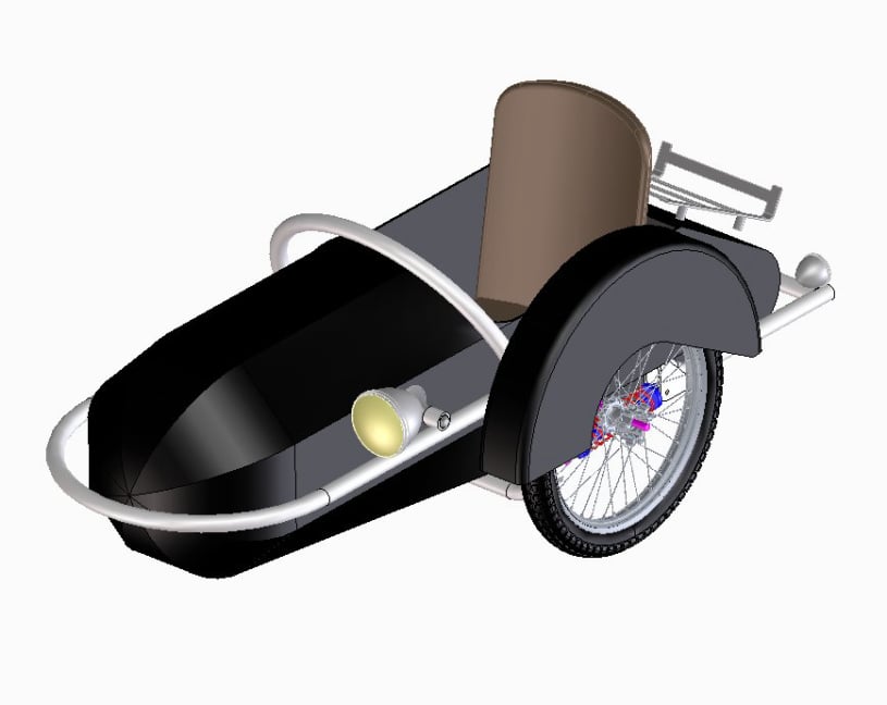
This page shows the design for the motorcycle sidecar and gives some guidelines for producing a sidecar suitable for a given motorcycle.
The chosen motorcycle was an R60/6 BMW. Not a hugely powerful machine and weighing 200kgs. So the design was decided to be a small lightweight sports chair, approximately 70kgs in weight in order to be appropriate for the bike. As a guide sidecar weight should be 1/3rd the motorcycle weight.
The developed design was based heavily on the classic Steib designs. These sidecars from Germany featured 8 segment "zeppelin" style bodies inside an external hoop frame. Originals were made from steel and were typically finished in black or drab olive paint.
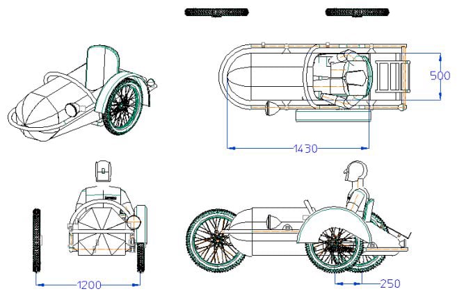
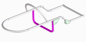
The CAD for the proposed design is shown here; modelled with a 5ft 10" passenger.
Width of the cab was decided to be 500mm with 1430mm of leg room.
These dimensions dictated the width of the frame. The wheel track would be on the smaller side at 1200mm without being too narrow.
Sidecar wheel lead was set to a nominal 250mm, but would be adjustable using the mounting points to the motorcycle. Likewise toe-in and bike lean would be adjusted the same way.
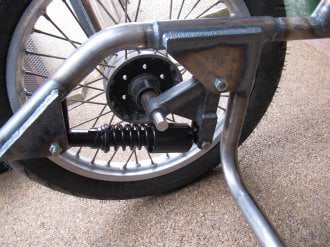
The frame featured a compact suspension arm with horizontal shock absorber and the ride height was dictated by a chosen wheel of 18" diameter.
The Frame was designed to consist of two main hoops curved around the same radius; one at the front of the sidecar and one over the top which would also act as a grab rail.
At the back a straight joining piece would be used between the frame sides.
Each side contained an S-bend partly as a styling feature and also to give a shape to house the suspension design.
A later addition was to add another loop under the chassis (in purple) to provide a mounting point at the back of the frame and also to strengthen the suspension pivot point.
The suspension pivots (in green) would be made from 6mm thick steel plate, cut on the mill as pairs to ensure symmetry.
The proposed suspension design was to have a horizontal shock absorber driven via a bell crank from the wheel. The pivot for the swinging arm would use roller bearings.
The arm was designed to fit the chosen wheel and axle assembly and to make sure the tyre was clear of the frame.
The swinging arm was made from 3mm thick 30mm box section and 6mm plate steel parts, plus some turned steel components.
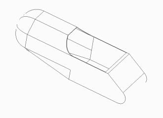
The sidecar bodywork was to have an octagonal nose section merging to a square section at the back. To make manufacture simpler, only 2D curves would be used so that no panel beating would be needed.
Also the top three sections would stop at the passenger opening so that in effect, it would only be required to merge the 5 lower front sections to into the 3 back sections
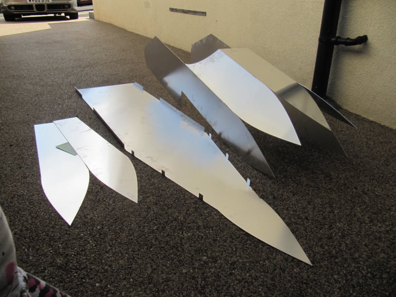
The plan was to produce drawings for the parts that would be laser cut and folded to make assembly easier and with less welding required.
Material was to be 1.5mm thick aluminium.
The top section of the sidecar including the sides, should be folded out of one piece to reduce welding an aid alignment.
The front "Zeppelin" nose would be made from shaped "gores" curved down to a point.
The base would have side tabs to help assembly and the lower quarter panels at the front would be twisted to merge the square back to the octagonal front.
AI Website Maker