Mobirise Website Builder

Geepstar Electrics

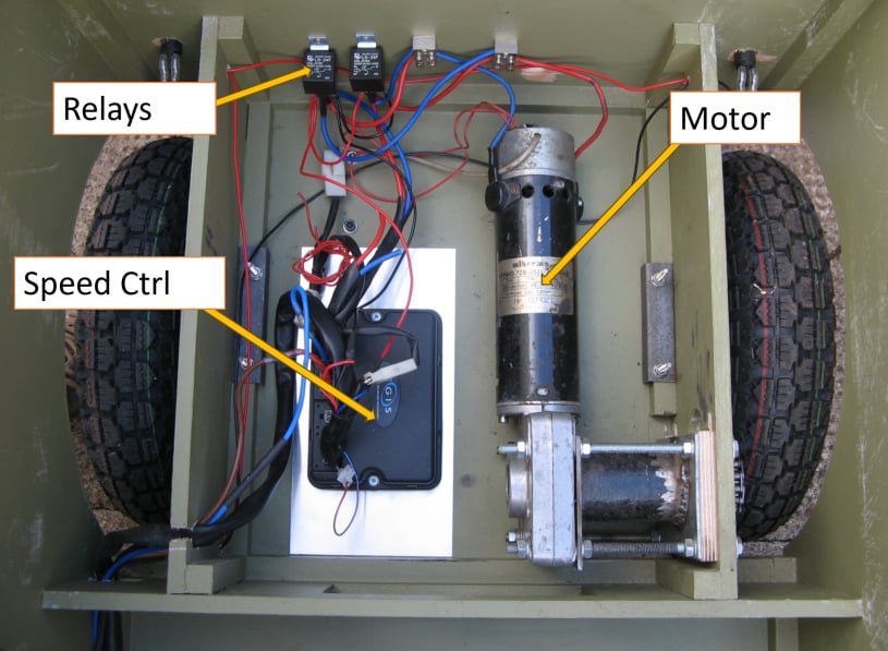
The basic electrics for the Geepstar were lifted from a scrap mobility scooter and were modified to suit.
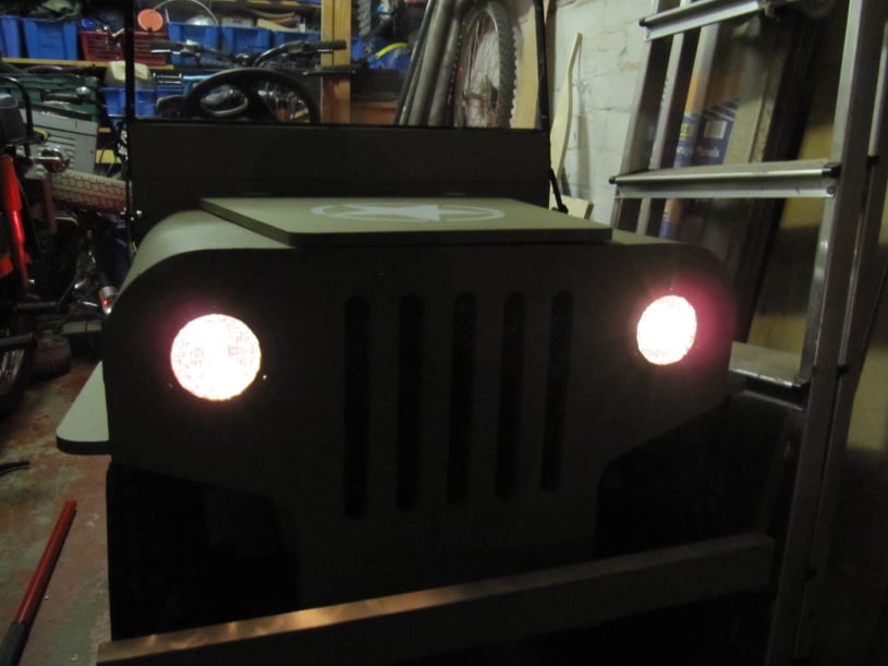
The donor scooter was a Karelmar 8mph model. Containing two 250w motors. The scooter had a forward / reverse control and another dial to set the maximum speed. Other features included a slow speed setting, freewheel control, auto-parking brake and lights.
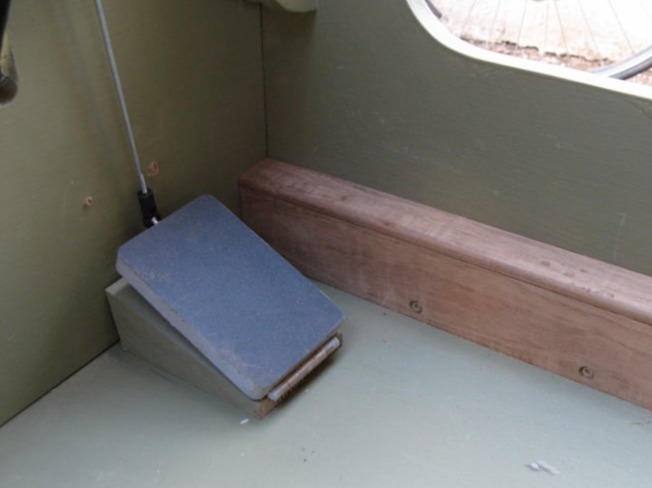
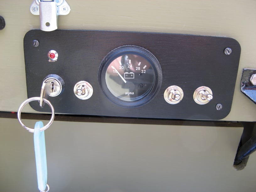
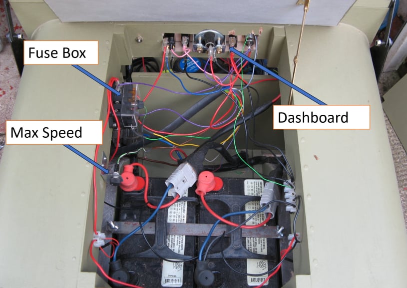
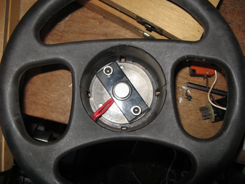
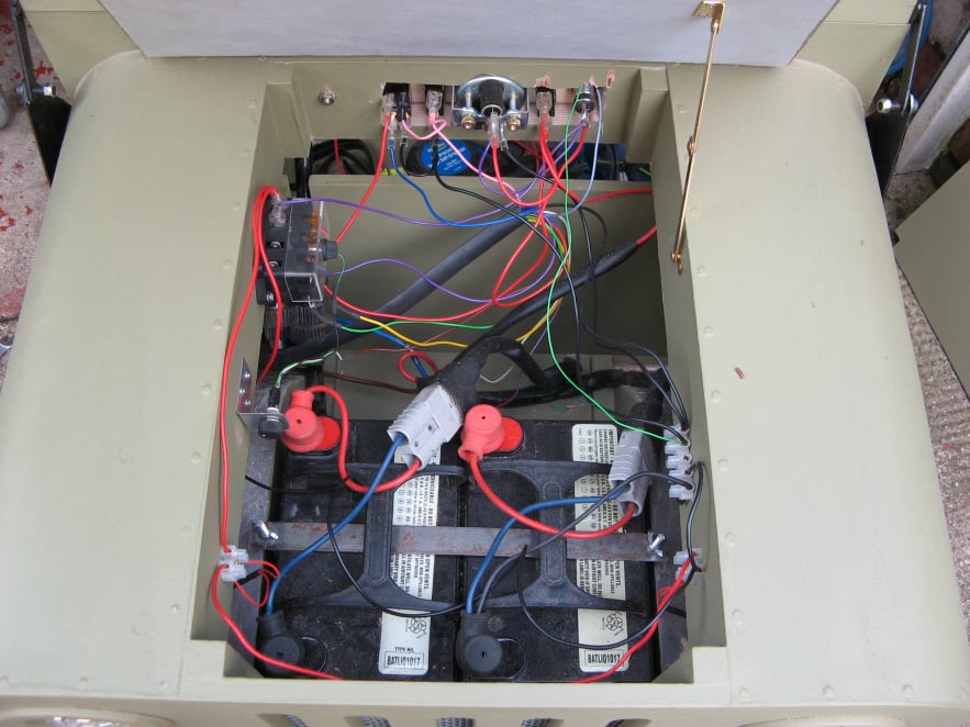
Originally the scooter was controlled by a "wig-wag" mechanism. This was a rocking bar on the handlebars, pulled by the right hand to go forward and the left hand to go backwards. This would need modifying so the speed could be varied by a pedal and the direction via a switch. The Geepstar wiring would also need to include the necessary fuses and an isolator switch to cut the power to everything.

Mobirise Website Builder

The lighting circuit was straightforward but because the purchased headlights had 12v bulbs these were wired in series. The Rear lights from the scooter were used with 24v bulbs.

All the bulbs were wired back to a switch on the dashboard and the power to the switch came from the main power cut out, via a fuse.

The motor was controlled via the scooter speed controller which included a switch to give a slow speed and a key switch to power the controller. This was all wired as per the original scooter. The top speed control was mounted under the bonnet so that maximum speed could be limited if needed.

Mobirise Website Builder

A throttle pedal was made as shown hinged from an angled mount to make it easier for the driver to press. The pedal was topped with some coarse sandpaper for grip and the base was drilled to hold the return spring. The wig-wag potentiometer used a 15º sweep each side for forward and reverse. It was mounted above the throttle pedal to be pulled by a simple rod and ball joint assembly taken from a radio controlled model.

The top pedal stop was important to ensure that the potentiometer didn't travel above the centre position, as this would put the Jeep into reverse.

Initially there were problems getting the motor to run despite using the standard scooter set up. Eventually the addition of an LED to read the error from the speed controller showed that the potentiometer from the Wig-Wag control needed to be in the exact centre position for the circuits to initialise and start to work. Once this was understood the electrics proved reliable.

Mobirise Website Builder

The dashboard was made from a piece of wood painted black. Drilled for the switches and a voltmeter.

The ignition switch was taken from the scooter and an LED was added to know when the circuits were ready and to help fault find any problems with the speed controller. 

The left switch was the FWD/Rev selector.
The second switch put the Jeep into a slow mode for congested areas.
The last switch was the for the headlights.

Mobirise Website Builder

The photograph on the left shows the under bonnet wiring.

Amongst the components was a fuse box and the max speed control from the scooter.

The bonnet was fitted with a lock, to keep the batteries isolated from the driver and prevent access to the maximum speed switch.

Mobirise Website Builder

Reversing the scooter was the next issue. Several options were tried which used additional switches or controls on the inputs to the speed controller. The problem was that any interruption to these control signals resulted in the speed controller going into fail-safe mode and cutting the power to the motor. Only a reset to the whole system would then get things moving again.

So in the end two relays were added to swap the polarity at the motor. These were 24v 30A automotive relays. They were only single pole and so two were needed (one for each wire to the motor). The relays were controlled via a double pole switch on the dashboard which also connected the slow speed signal so that the reverse speed would always be half of the forward speed.

Mobirise Website Builder

The horn was a cheap 24v one from an auction site which was wrapped in Duck tape to muffle its sound. This changed the tone of the horn from an aggressive 'Waaaaah' noise, to a friendly "Toot-toot".

All the electrical connections were crimped and soldered for security.

No Code Website Builder