Geepstar Axles and Steering
An articulated front axle was chosen for improved traction when running over uneven surfaces. The steering system was also modified to include a reduction gearbox and Ackerman angles on the steering arms.
An articulated front axle was chosen for improved traction when running over uneven surfaces. The steering system was also modified to include a reduction gearbox and Ackerman angles on the steering arms.
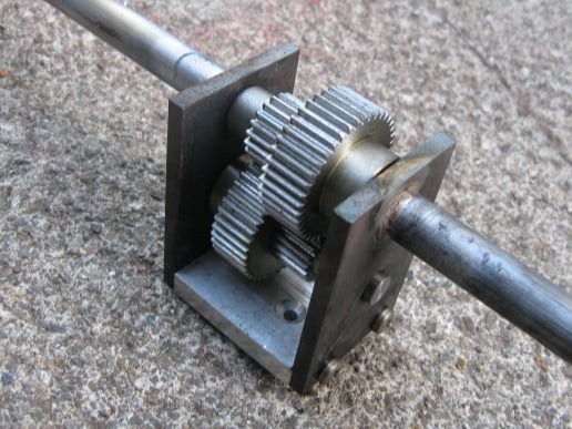
The steering column was modified to include a reduction ratio of 4:1, by combining two 2:1 reductions on a lay shaft. The lay shaft type gearbox was used to ensure the direction of the steering was not reversed.
The gears were ordered from Technobots and were Mod 1 and were of 40 teeth and 20 teeth (2 of each).
The gearbox had 2 parallel shafts 30mm apart.
The two sides were machined as a pair and then mounted on an aluminium base. Two pieces of 14mm tube were inserted into the upper holes and brazed in place. Alignment of these tubes was maintained with a length of threaded bar.
The smaller gears had 8mm holes in them and so these were expanded on the lathe to 10mm to match the larger gears. All the gears were also cross-drilled and tapped to take drive pins.
The 12mm threaded rod lengths had the ends reduced to 10mm to suit the gears.
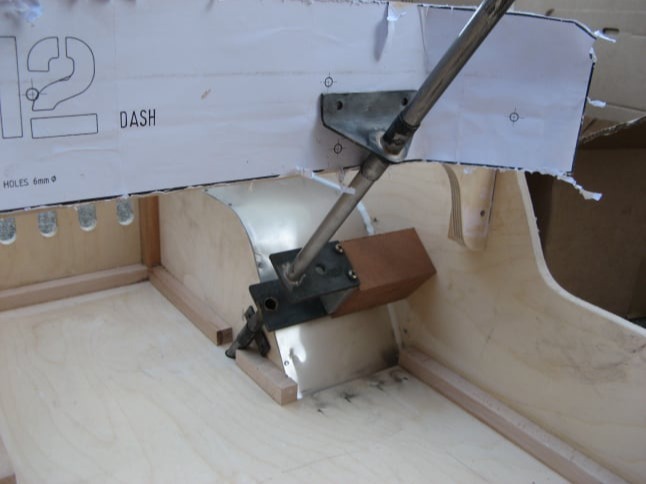
The gearbox was mounted on a block of hard wood screwed to the inside of the body.
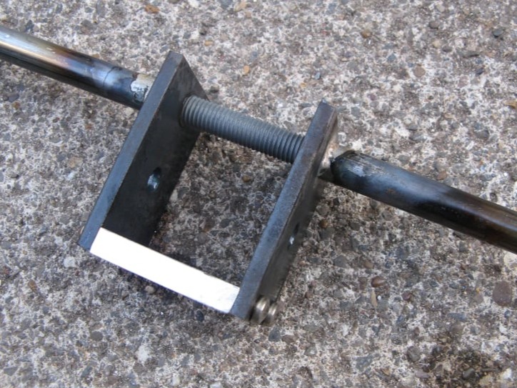
Upper and lower mountings were made as shown. They were both made from a larger piece of pipe drilled out to be a snug fit on the 14mm steering column and brazed to a mounting plate.
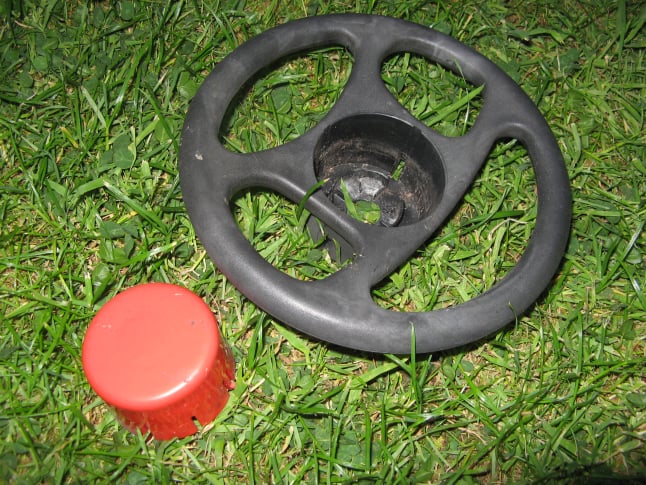
The steering wheel was taken from a child's toy car which someone had abandoned in the street. The wheel was broken on the back and had a squeaker horn in the middle.
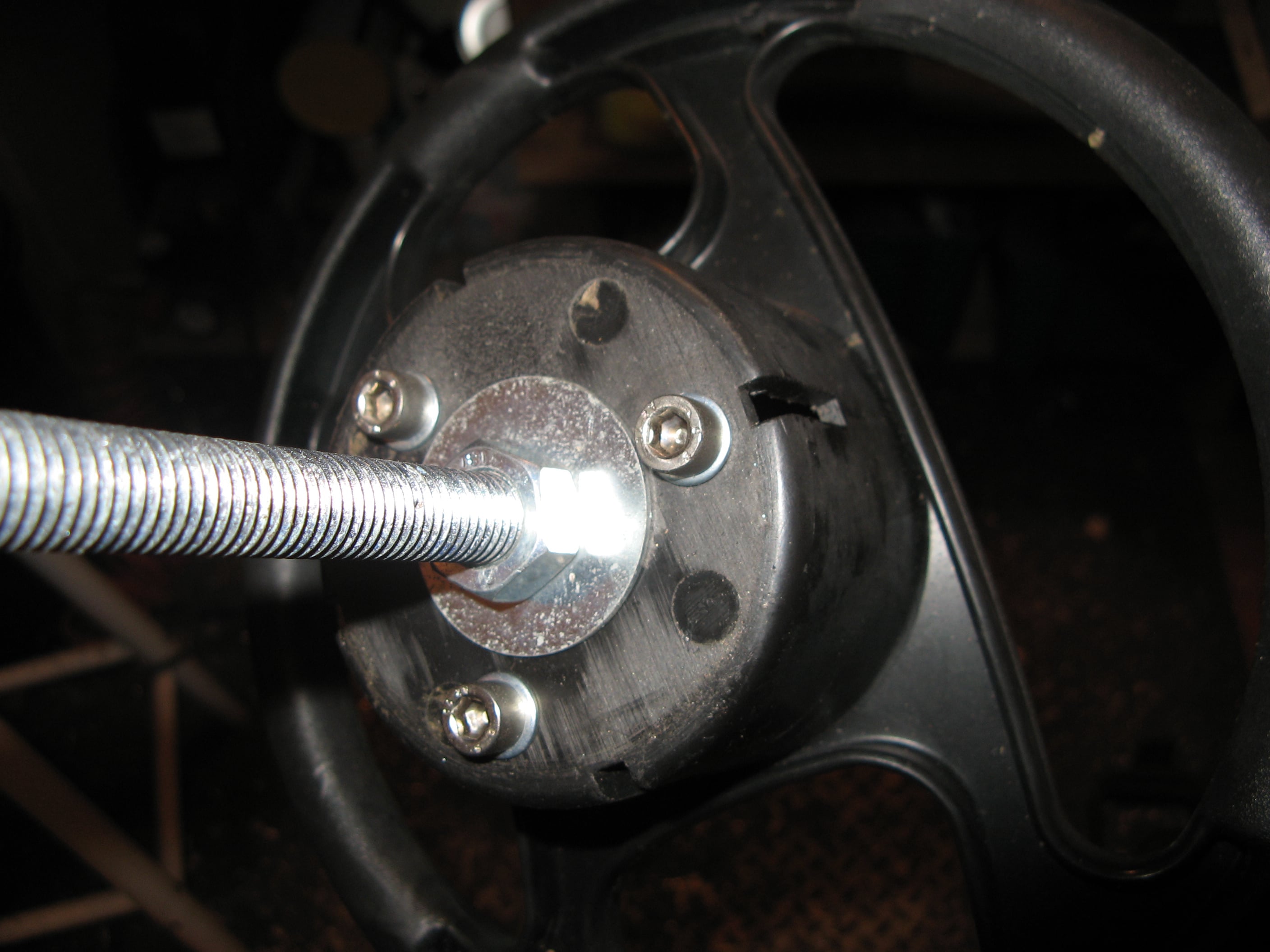
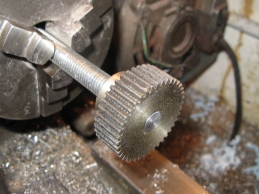
A new metal boss was turned up on the lathe to fit inside the steering wheel boss. This was fixed in place with three M6 screws. The new boss was tapped M12 x 1.75mm match the steering column threaded rod.
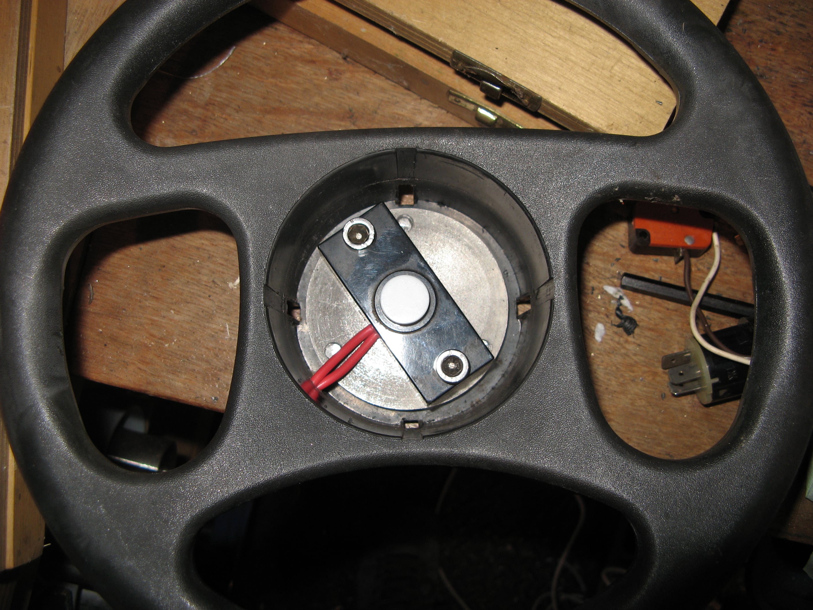
Inside the steering wheel boss, a door bell switch was modified to act as a horn button.
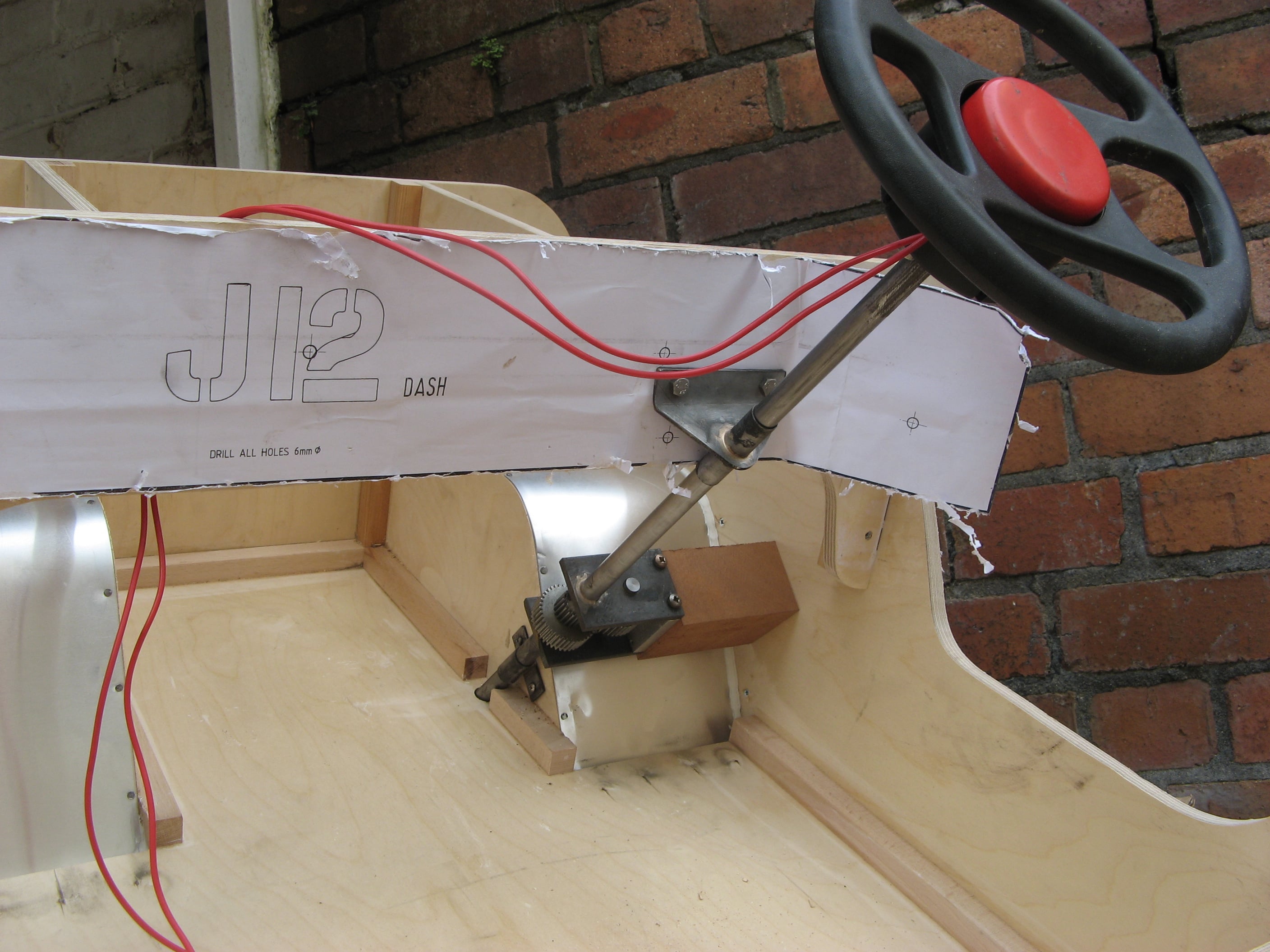
The completed steering column
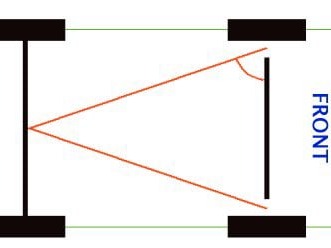
The design was adapted to accommodate Ackerman geometry. Ackerman steering allows the inside front wheel to turn sharper during a turn to reduce tyre scrub.
This was done by stretching a piece of string from the mid-point of the rear axle across to each steering pivot.....
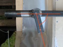
The angle formed between the string and front axle is the Ackerman angle and this was transferred to the steering knuckle as shown.
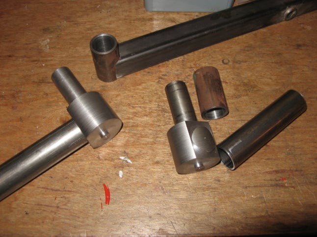
Another modification was to use plain shafts for the steering pivots, rather than the threaded rod. This was because no 20mm threaded rod was available.
The picture above shows the components. Each steering pivot was a piece of 50mm steel bar with a section reduced to 20mm to fit in a sleeve on the end of the axle.
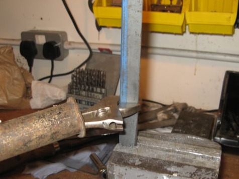
The link to connect the column to the steering bar was twisted by clamping in the vise and using a bar on an adjustable spanner to put the required twist in place.
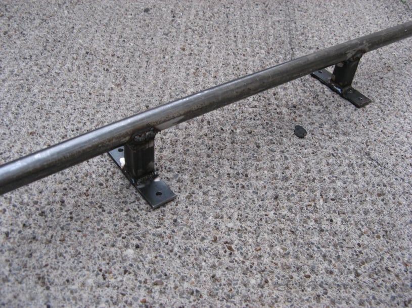
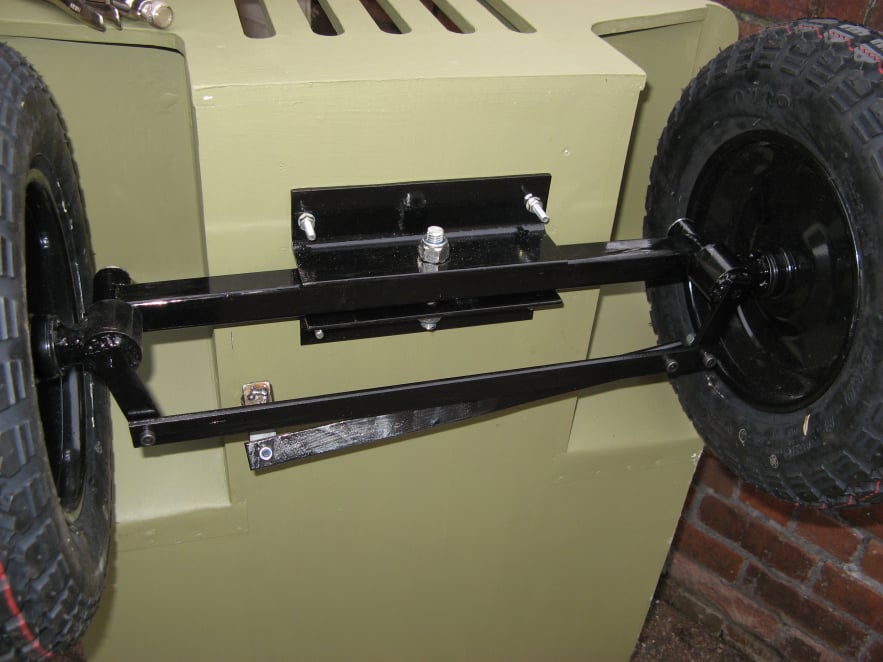
The rear axle was made exactly to the plans. The parts were assembled to the chassis and clamped in place before welding to ensure that it would be an exact fit. Once tack welded in place, it was removed and seam welded for strength.
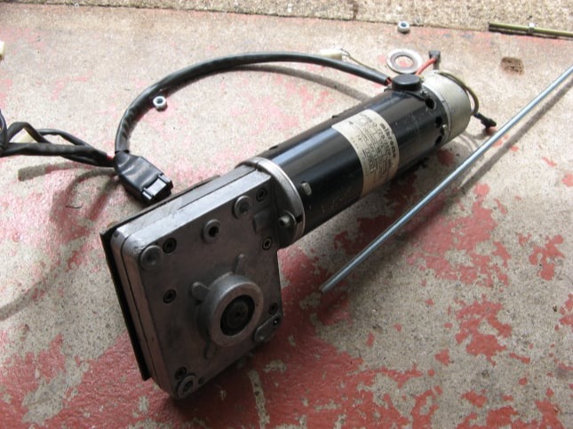
The motor and electronic speed control unit were take from an 8mph scooter.
The motor was a 250W 24V DC motor with a built in brake.
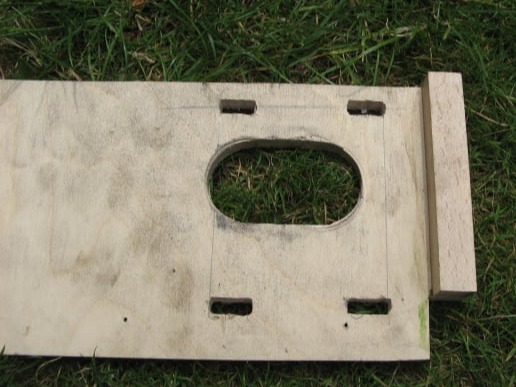
A double thickness mounting was used to space the motor inwards by 12mm so that the motor sprocket would be close to the inner wing enabling the wheel to be mounted without sticking out too much.
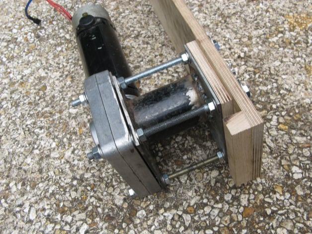
To fit the motor into the rear of the jeep, first a new plate was welded to the existing bearing housing. Lengths of M8 threaded rod were used to secure the motor through the housing and the new mounting plate into a double thickness section on the rear inner wing. The inner wing was slotted to allow some motor movement to tension the chain drive.
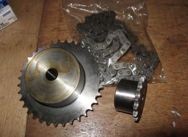
A 3/8" chain and sprocket set was ordered from Technobots. The sprockets chosen were 35 teeth and 17 teeth so that the original 8mph scooter speed would be reduce to about 5mph on the new, larger wheels.
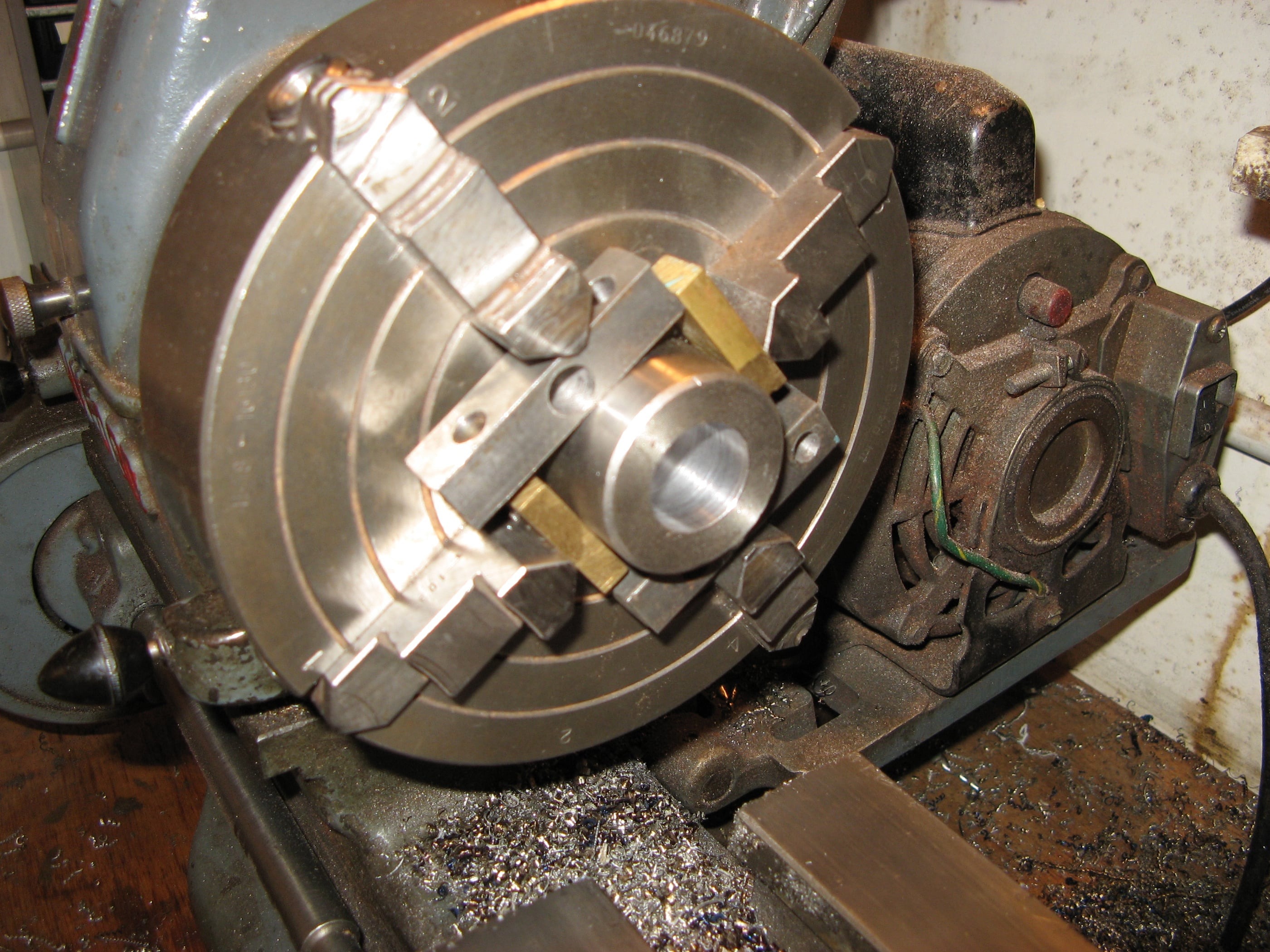
The purchased motor pinion was bored out to fit the motor shaft (20mm) and drilled to accept two 6mm grub screws. These screws would locate in the shaft key way.
The wheel sprocket was bored out to 28mm to be a clearance fit on the shaft. Then the outside of the boss was machined to have a step, which would fit inside the wheel hub without the bearing seal. On the opposite face another recess was cut to take the new needle roller bearing.
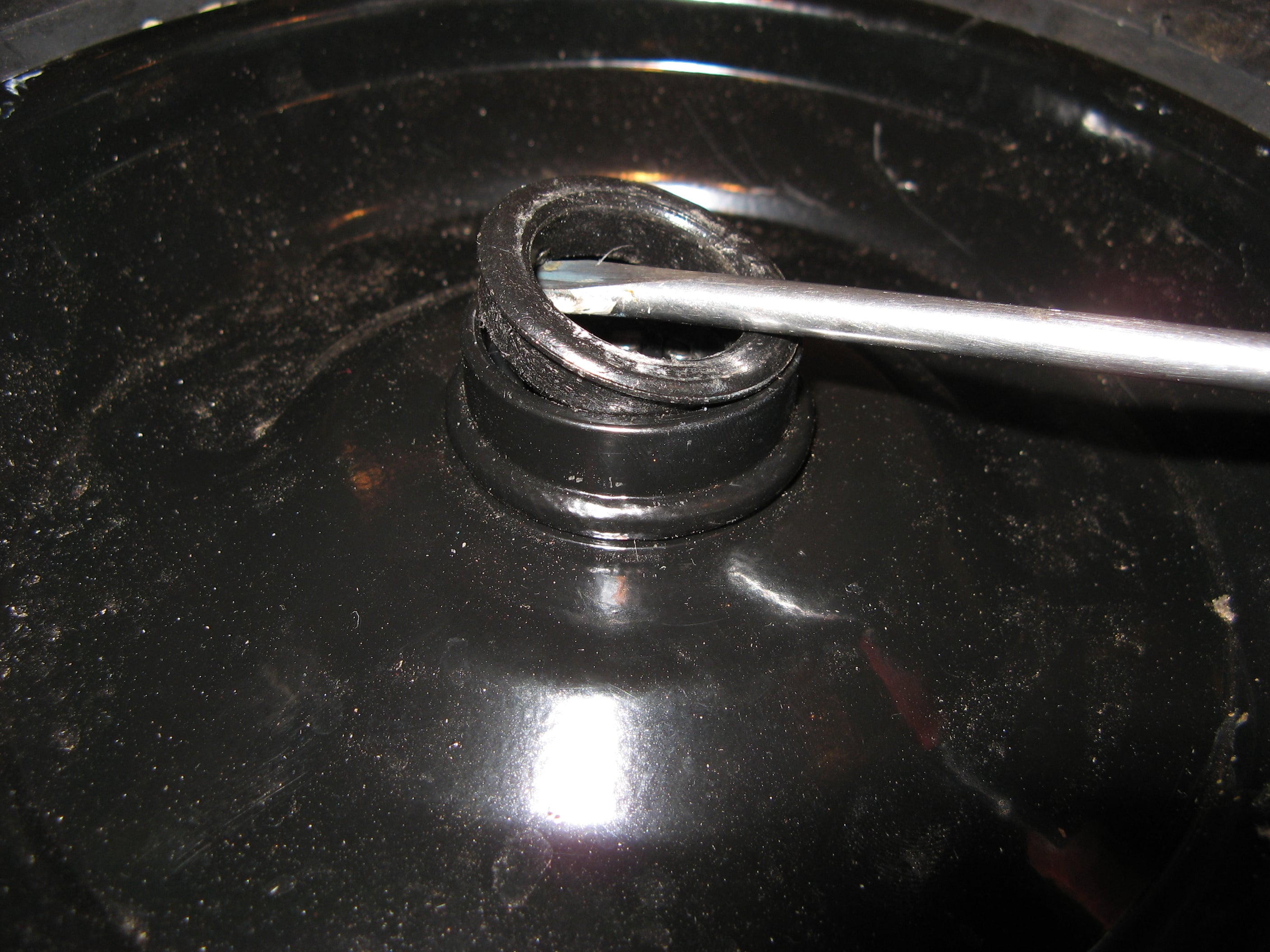
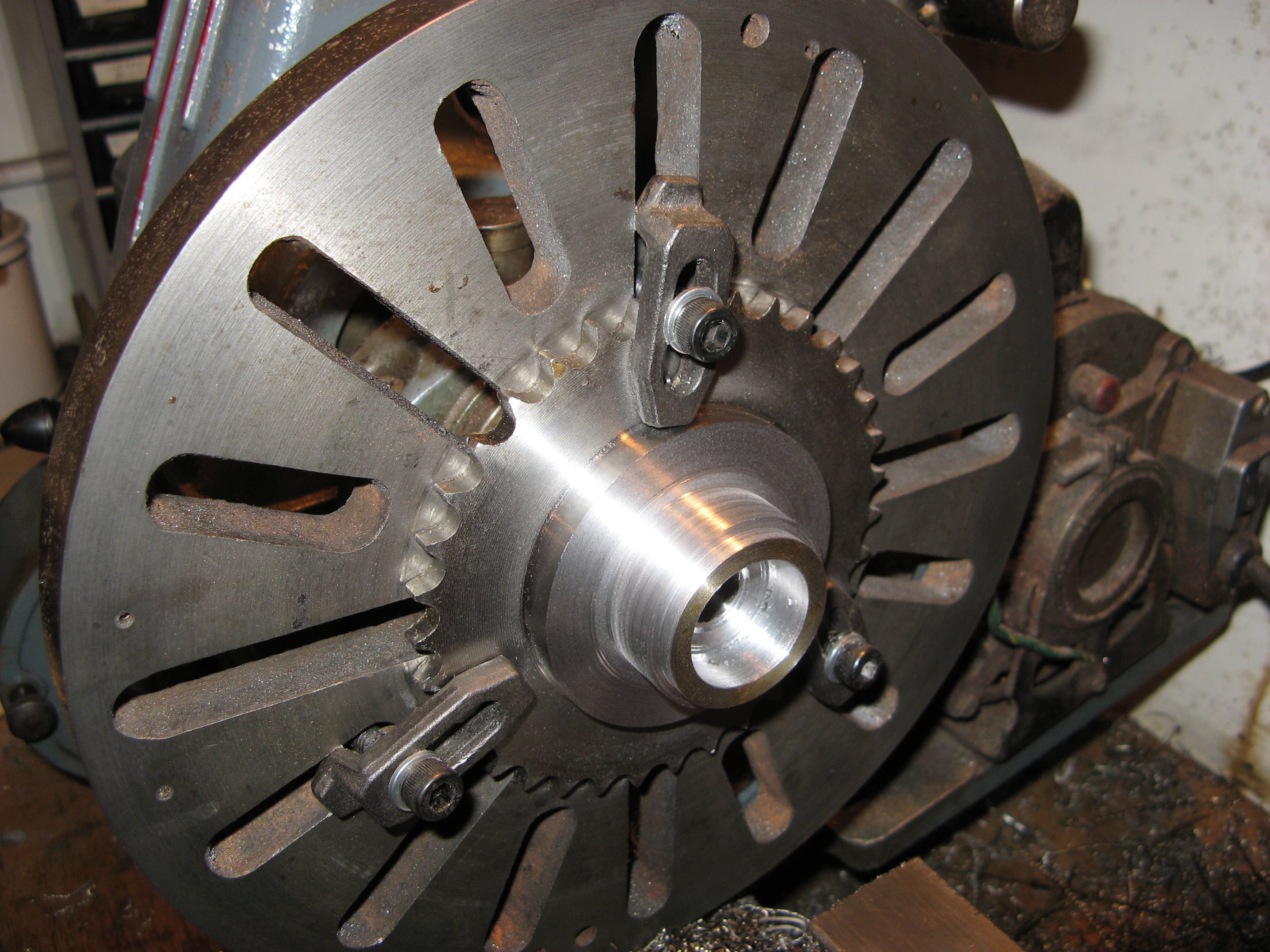
On one rear wheel, the inner wheel bearing seal was removed.......
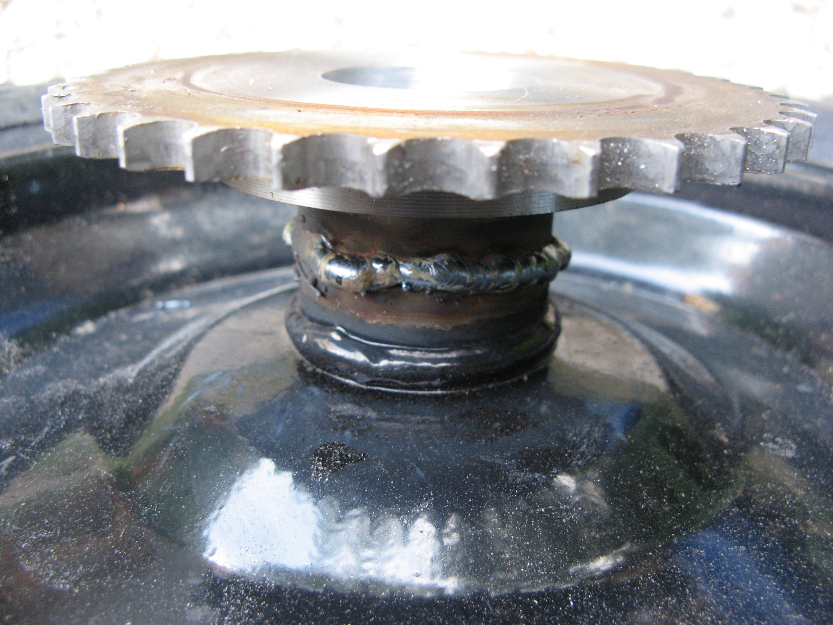
.....and the sprocket welded in place
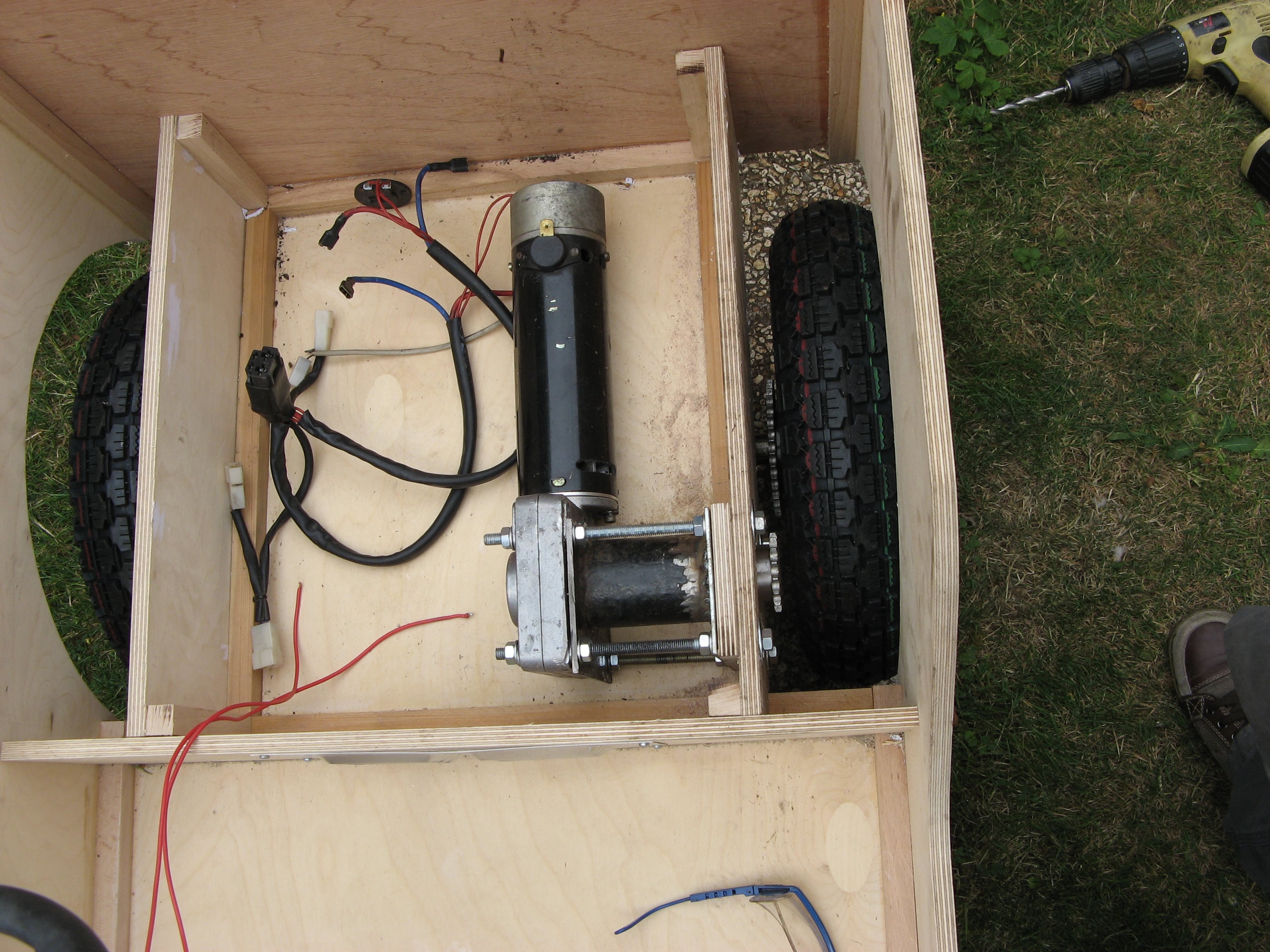
Checking sprocket alignment and chain clearance on the final motor drive system.

Free AI Website Software