Tailstock DRO
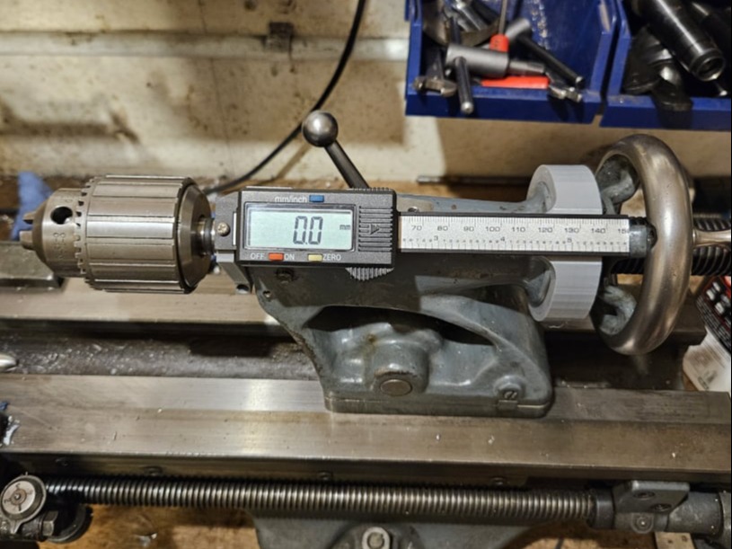
This 3D print project was designed to mount a cheap digital caliper on the tailstock of the ML7 lathe. A useful feature to enable accurate depth drilling and also helpful on any lathe with worn graduations on the barrel.
This 3D print project was designed to mount a cheap digital caliper on the tailstock of the ML7 lathe. A useful feature to enable accurate depth drilling and also helpful on any lathe with worn graduations on the barrel.
The basis for this design was a cheap digital caliper from an online retailer. A plastic bodied one was chosen instead of steel for it's price point and also to be much easier to modify than a hardened steel one.
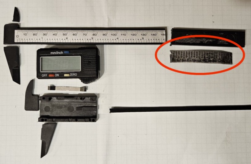
This photo shows the caliper cut to separate the read head from the measurement jaws.
The overall length of the stem was shortened by cutting at the 150mm mark.
Note that the label in these cheap calipers is what holds the encoder signal so care should be taken to avoid damage. The part circled in red is the discarded label end, turned over to show the data pattern.
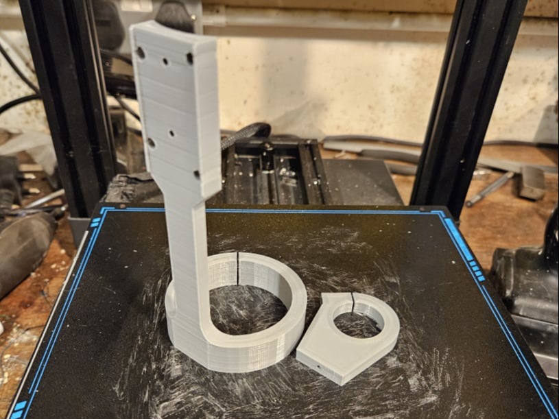
Two 3D print parts were created. One clamp for the neck of the tailstock barrel and another part to hold the digital display unit. This larger part was designed to clamp to the tailstock, near the hand wheel. Click on the image above to download a .zip STL file of the two parts.
The clamp part should be threaded with an M2.5 tap.
Both clamps can also be fitted with 2.5mm nuts and 16mm long screws.
The back of the display unit can be used to accurately mark the the hole positions in the back plate of the read head. The holes in the read head must be 3mm diameter and counter-sunk on the top side.
The holes in the mounting bar can then be tapped with an M3 thread.
The back plate can be attached to the mounting bracket using short M3 counter-sunk screws.
The front of the read unit can then attached using the access holes in the mounting bracket.
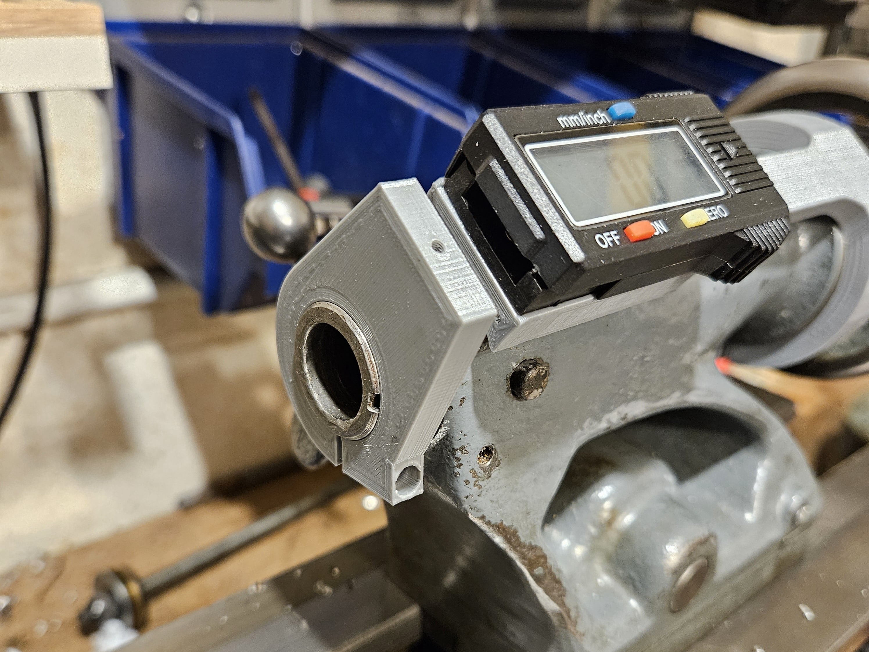
With the the tailstock handle removed, the assembled read head and bracket can be slid into place as shown allowing for access to the "keeper plate" for the handle.
The handle should then be replace along with the keeper plate and retaining screw.
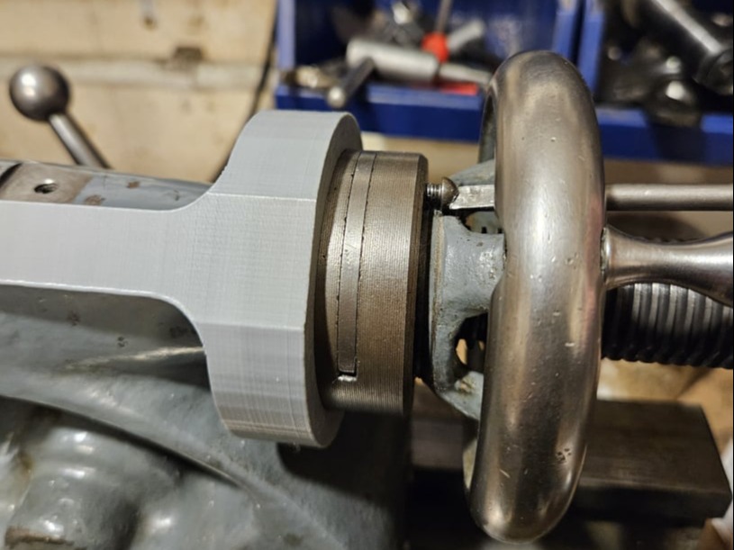
With the display rotated to the desired angle, the clamp screws can be tightened.
The nose clamp can be installed next, rotated to match the angle of the display.
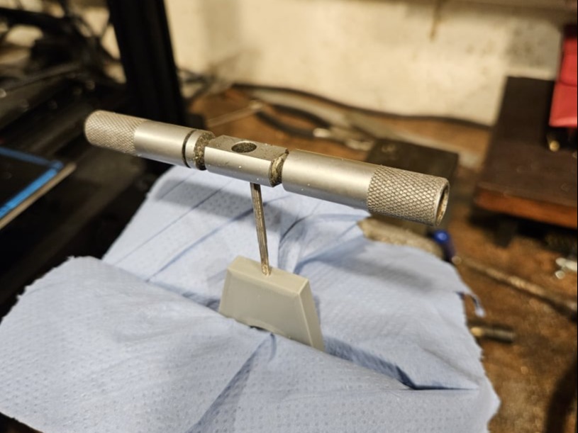
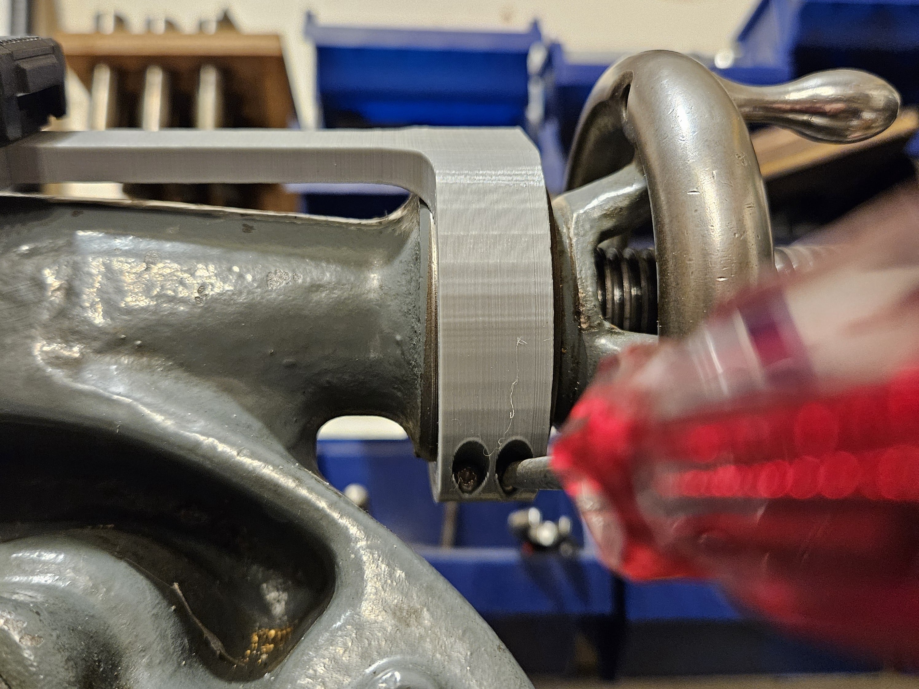
The measuring bar must be drilled to take a 2.5mm screw and then it can be fed into the read head and secured to the nose clamp as shown.
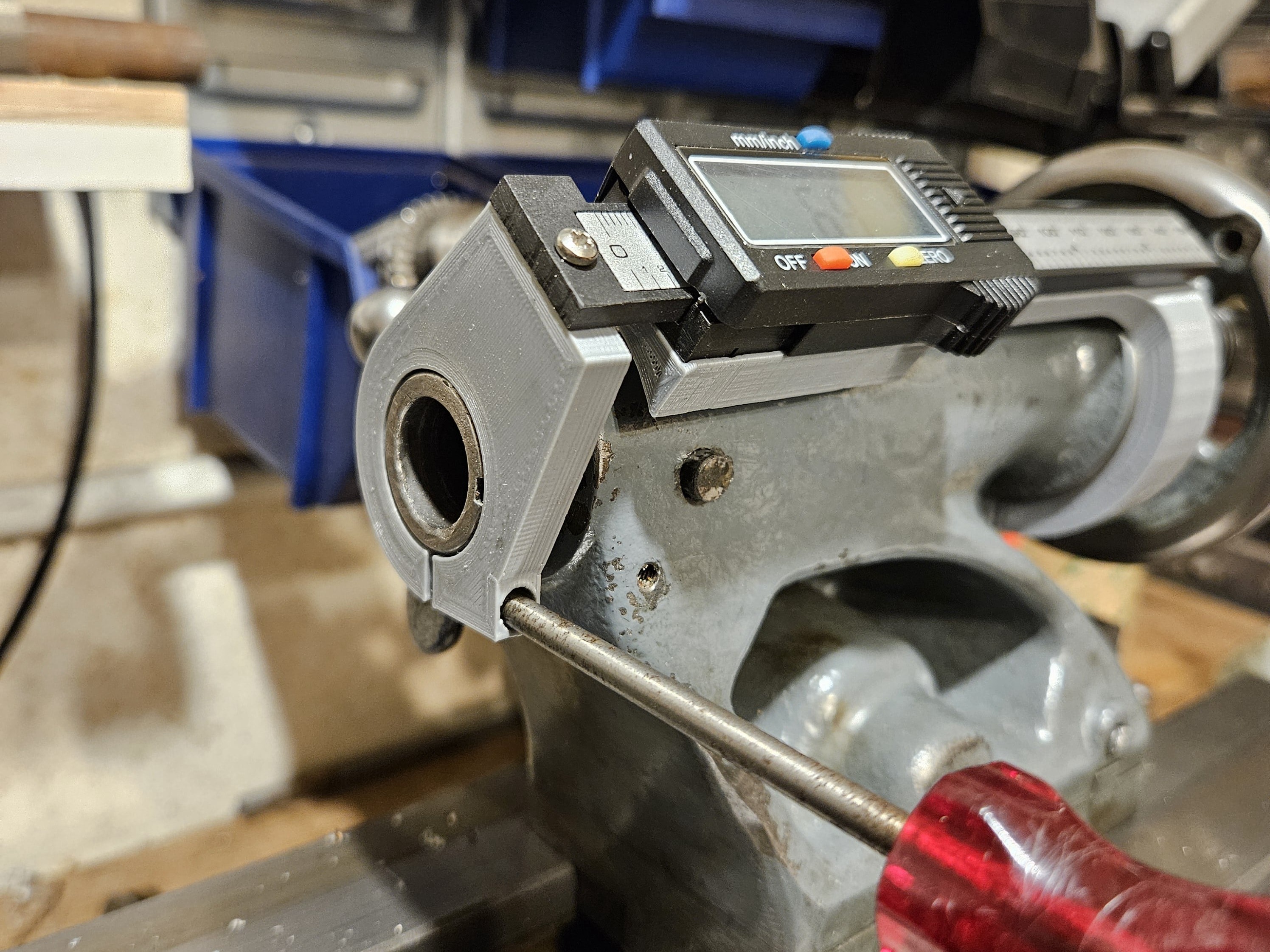
Once the free motion of the system has been checked, the nose clamp screw can be tightened.
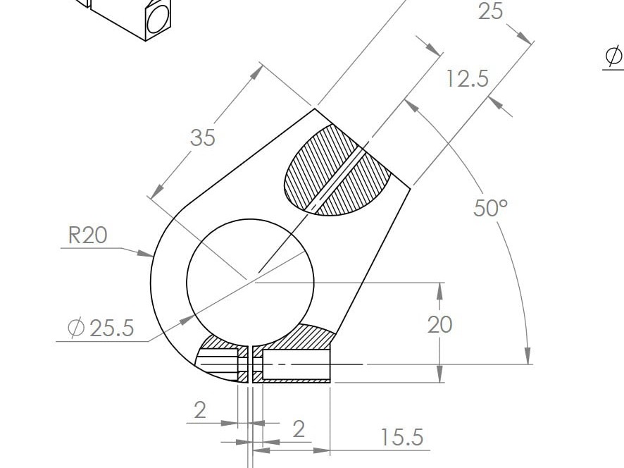
The drawing for for parts can be viewed by clicking the image above.
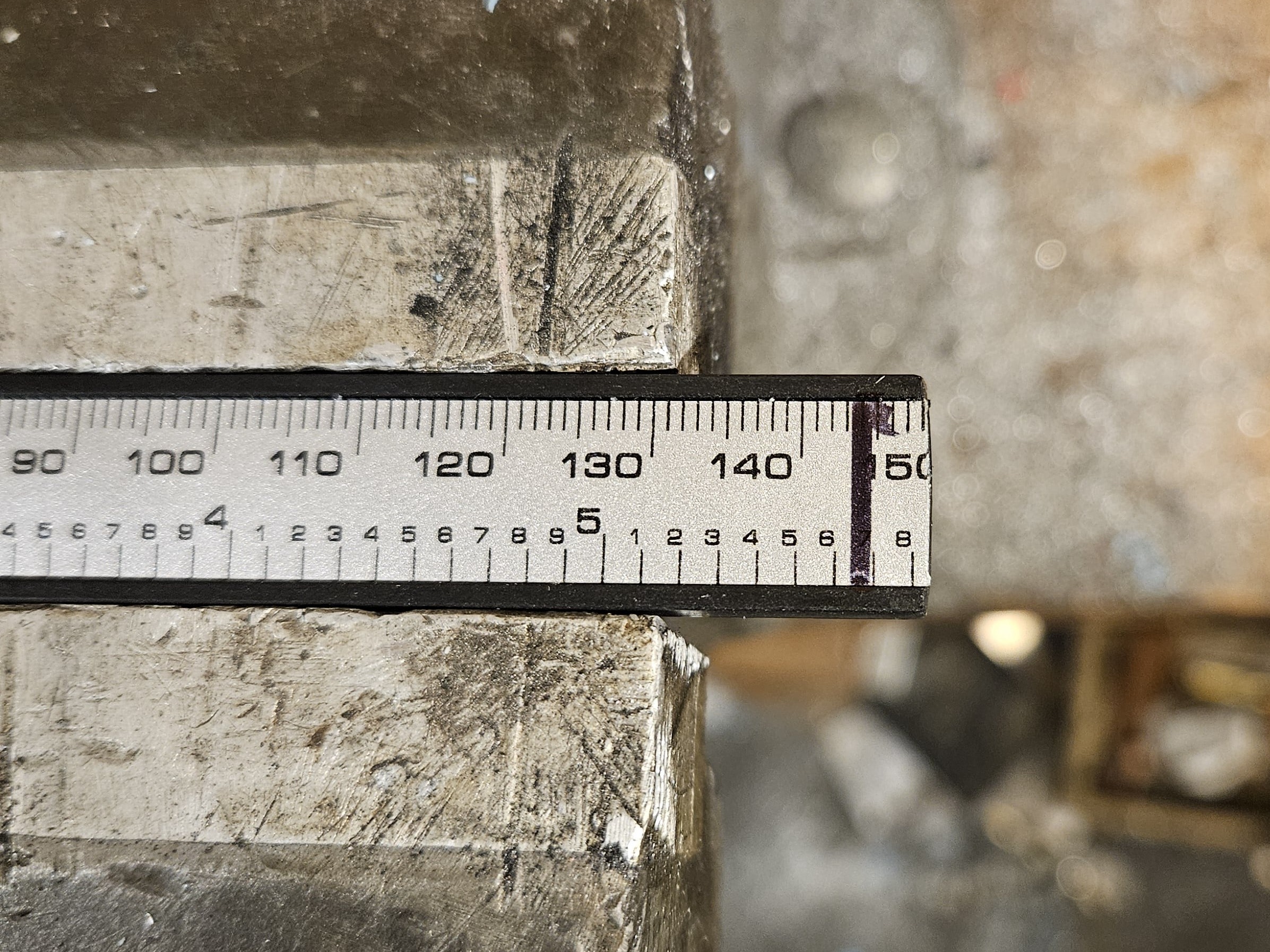
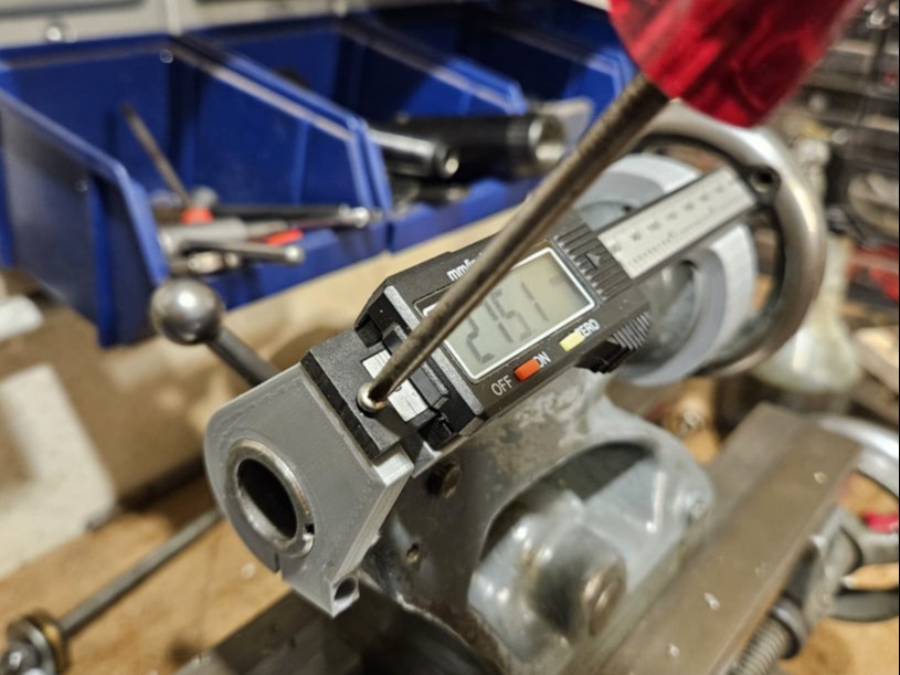
After fitting all the parts. It was discovered that the measuring bar could be shortened to the mark shown here without limiting barrel travel.

Free AI Website Creator