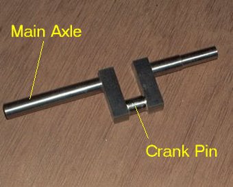
Mobirise Website Builder

Stuart No 1
Crankshaft

The critical objective with any crankshaft is to ensure that the crank pin and the main axle are parallel in all planes. If this is not the case there are awkward twisting actions applied to the connecting rod causing tight spots and binding. The other dimension to get right is the linear distance between the crank pin and the axle as this defines the stroke of the engine.

Mobirise Website Builder

The crank webs were machined as a pair to ensure that they were identical.
The two blanks were screwed together and the 2 holes were bored using the 4 jaw chuck on the lathe to get them exactly parallel.
When this was complete the web were cut to length using a hack saw, removing the securing screws in the process.
Also - the main axle and crank pin were cut to length. Both were faced square in the lathe and the axle was set to run true in the 4 jaw so that it could be centre drilled accurately in both ends.

Mobirise Website Builder

The rods and webs were assembled and cross-drilled in the drill press to allow pins to be used to hold the assembly together. Both crank webs were clamped together in the drill vice to ensure that they were pinned in line with each other.
The assembled crank was silver soldered together. It was left to cool slowly in the hearth so that it didn't harden or distort.

Mobirise Website Builder

The crank was mounted on the lathe between centres to turn the webs to their final thickness.
The radii on one end of the webs was also turned in this setting.
Also in this setting the reduced diameter section of the axle was turned to size.

Mobirise Website Builder

The next process was to remove the section of the axle between the webs and then machine the inside faces of the webs. The bulk of the removal was done with a hacksaw.
Then 2 blocks of steel were drilled to hold the crank axles and locate a centre to turn the workpiece. The radii on the other end of the crank webs was also cut in this setting.

AI Website Creator