Mobirise Website Builder

Stuart No 1
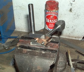
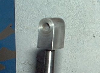
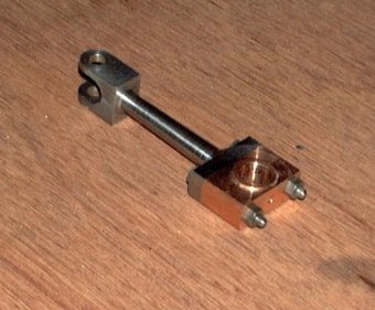
Connecting Rod and Big End Bearing

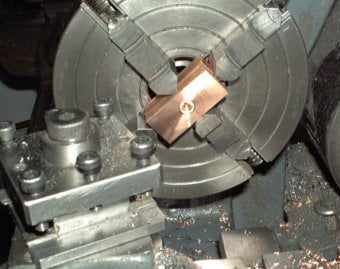
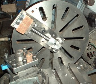
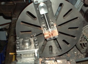
It is important that the 2 holes in the connecting rod are parallel in both planes for the engine to run smoothly.
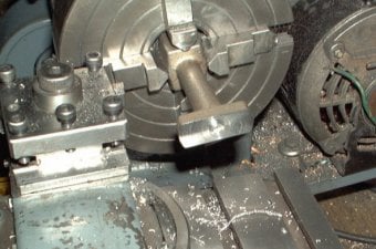
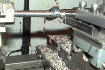
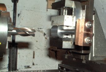
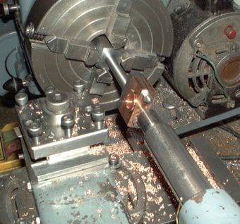
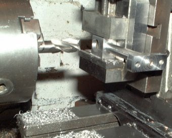
The process described here machines both the critical holes using a boring tool on the face plate, to keep things as parallel as possible.

Mobirise Website Builder

The con-rod was mounted in the 4-jaw chuck as shown here and set to run true. Then the locating spigot at the far end was faced off and centre drilled so the tailstock could be added for support.

Mobirise Website Builder

With the tailstock in place, the con-rod stem was turned, along with the top and bottom faces of the foot. The outer diameter of the foot was tidied but left oversize.
The top slide was used on a 1º setting to get a taper on the stem.
Before the con-rod was removed, the 2 bolt holes were marked the base of the foot.

Mobirise Website Builder

The bronze to make the big-end bearing was cut in half and the 2 halves made good in the 4-jaw chuck.
The 2 parts were stuck together with double sided sticky tape and mounted together in the 4-jaw chuck as shown. An indent to match the spigot on the base of the con-rod was drilled in the middle of the exposed face and then the face was machined to take one of the bronze parts to the final thickness. A 2.5mm hole was then drilled right through the 2 parts.
Then the 2 parts were reversed in the chuck and the other half was machined to its final thickness.

The 2 bearing halves and the con-rod were now assembled together. The shank of a 2.5mm drill was used to hold the 2 halves of the big-end together. The 2 bolt holes were drilled right through the set of parts so that they could be bolted together.

Mobirise Website Builder

The 2 critical holes on the con-rod (little end and big end) would be machined on the faceplate but the top of the con-rod wouldn't fit through the gap in the lathe bed. So first it was placed in the vertical slide and machined on both sides, but left oversized.

Mobirise Website Builder

To bore 2 parallel holes in the con-rod the assembled parts were mounted on a piece of gauge plate, which was then bolted to the faceplate of the lathe. The gauge plate could be moved around on the faceplate whilst still maintaining a common reference, so that both holes could be bored parallel, even when re-centring the work piece.
The assembly was held with a single bolt drilled and tapped into the top end of the con-rod and the two big end bolts at the bottom. This mounting process allowed the con-rod to be flipped over so that both sides could be machined. The top bolt hole would be machined away once the top slot was created.

Mobirise Website Builder

This image shows the set up for the big end bearing which was bored to size. The shoulder on the other side was cut by reversing the part on the gauge plate.

Mobirise Website Builder

To create the beveled sides to the bearing,  the con-rod was held between the 4-jaw and the 2.5mm hole drilled previously.

Mobirise Website Builder

When the con-rod was clamped on the crank-pin for the first time it was a little tight although could be rotated with some force.
Then metal polish was used with progressive tightening of the big-end bolts to help it bed-in. Once a smooth turning fit was achieved the polish was cleaned out and replaced with light oil.

Mobirise Website Builder

Some filing buttons of the correct diameter were made to form the correct profile on the top of the con-rod.

Mobirise Website Builder

The assembly was placed back on the vertical slide to machine out the forked end profile.
This was done by using a milling cutter to, first, drill a hole of the correct diameter and then open the hole out into a slot.

No Code Website Builder