The valve sets the timing of the engine. However it actual has only two critical dimensions - the overall length of the valve and the length of the inside recess.
The width of the valve is unimportant as long as it covers the port holes.
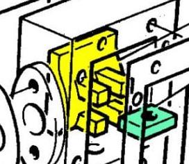
It is also important that the valve is allowed to float on the valve rod as this enables the steam pressure to seal the valve against the port face.
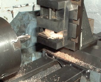
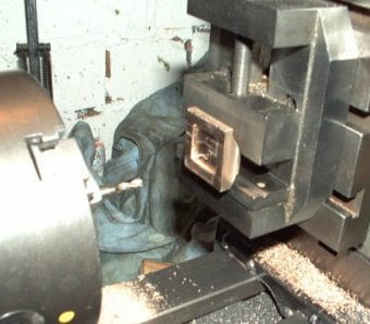
The vertical slide was used to cut the outside of the valve and machine the overall length to final size.
The vertical slide was also used to mill out the inside recess. The width and depth of this feature were unimportant, but the length was made to drawing and centred about the overall length.
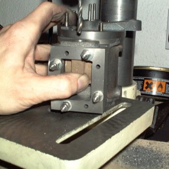
The hole for the valve rod was drilled to suit by assembling the steam chest and cylinder and holding the valve block in place, as shown here.
Once this hole was completed, a slot was cut perpendicular to the hole using a small milling cutter. This slot would hold the captive nut and allow for timing adjustment.
To get the valve and port face to seal the mating surfaces was smoothed on very fine wet and dry paper (1200 grit) on some plate glass.
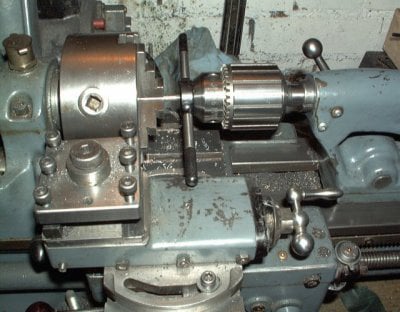
The valve rod thread was cut in the lathe, using the tailstock against the die holder to keep things square. The chuck was turned by hand to cut the thread.
The valve adjuster nut was a simple rectangle of steel drilled and tapped. It was a loose fit in the valve locating slot to allow the valve to seal under the steam pressure.
HTML Website Builder