Mobirise Website Builder

Steam Launch - Boiler Build

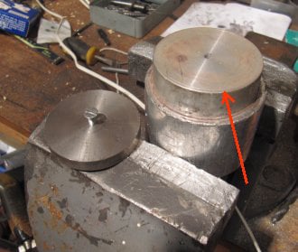
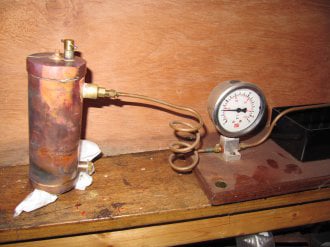
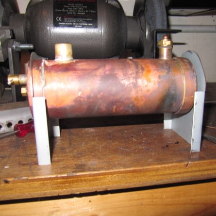
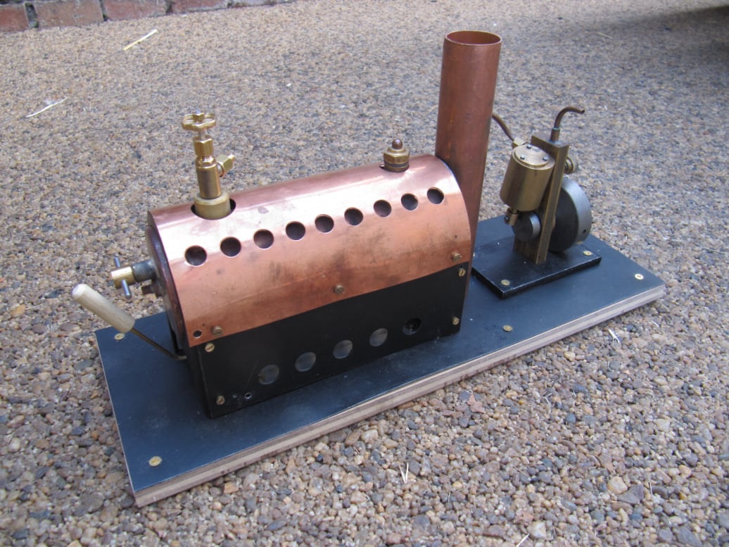
The pressure vessel for the steam plant was designed to operated at 30psi and provide the oscillating steam engine project with enough steam for 15 to 20 minutes of run time.

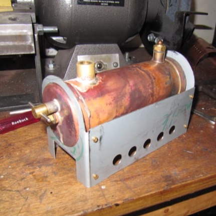
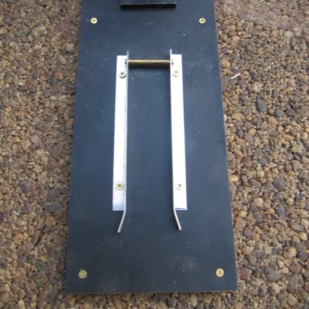
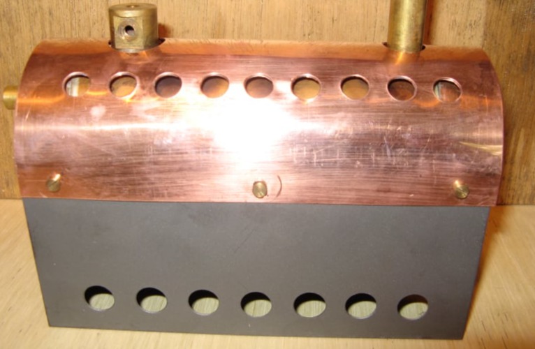
Ultimately the steam plant was to be used in a model boat and so the firebox housing was designed to have the lowest profile possible, whilst still providing enough space for solid fuel firing.

Boiler Description

To start, the copper tube for the pressure vessel should be cut to length and the ends filed as flat as possible. Exact straightness of this edge is not critical because the end caps would go over the ends of the tube.
The tube should be marked along it's length and then holes were drilled along this line to take the safety valve bush and the steam take-off port.
The end plates can be made from the same thickness of copper. In fact a piece of the copper pipe can be cut, annealed and opened out to give a flat sheet to work from.
Two discs are then cut by hand, of a diameter of the copper tube plus 25mm. They should be drilled in the centre.

Copper is the best material for a pressure vessel due to its mailability, conductivity and ease with which it can be joined. Bushes for fittings should be made from bronze where possible. Brass not being recommended as it can suffer from a process known as dezincification over a long period of time; but for a boiler operating at these pressures brass could be considered suitable with an awareness that this "corrosion" should be checked for periodically.

Silver solder is the only process suitable for joining the pressure vessel components. Soft solder not being strong enough at elevated temperatures from a safety and reliability point of view.

The firebox was made from 0.5mm steel sheet but brass or copper could also be used. Aluminium is less good due to its lower melting temperatures. BBQ aerosol paint was used to finish the firebox housing.

Mobirise Website Builder

To create the flanged ends a former should be turned from aluminium of the same diameter as the copper tube. This former should have a slight radiused edge (arrowed), to allow an easier forming process on the copper.

A top-cap or thick washer arrangement (shown resting on the left) is also needed to hold the part during forming and for this design of end plate a suitable screw should be added in the centre to hold the work.

Mobirise Website Builder

The forming process is a repeated cycle of annealing, cooling, then forming. These steps will need to be performed, perhaps 8 or 10 times to get the final form of the end plates. A soft brass or plastic hammer is recommended to avoid marking the copper.

Annealing is a simple process - heat the part to glowing red and then cooling/quenching. (Failure to anneal can lead to fracture of the copper which work hardens as it is formed).

Before removing the finished part from the jig, the jig can be placed in the lathe and the edge of the flange tidied up with light cuts from the parting tool.

The centre stay is a simple turning job but a note should be taken that copper is rather "chewy" to turn. A sharp tool helps and light cuts should be taken to get the best finish. The stay should have a shoulder turned on each end to suit a 2BA thread.

Three bushes are needed for the safety valve, steam take-off and the level plug and these are made on the lathe . The parts should be shouldered parts to match the holes drilled in the boiler shell.

The safety valve is a homemade part with a thread of 5/16" x 32 tpi. The steam take-off would have a thread of 1/4" x 40 tpi to suit a purchased manifold valve and the level plug is a smaller bush with an internal thread of 3/16" x 32tpi.

[Note : If a safety valve is to be purchased, a Mamod part is suitable and therefore the bush should be tapped 1/4" x 26tpi.]

As a general rule 40tpi threads are best for permanently fitted components and copper washers can be used to set component orientation.
32tpi threads are more suitable for components that require regular removal such as filling caps. These components can use fibre washers to seal them.

Mobirise Website Builder

The end caps can now be assembled with flux paste and held in place with the centre stay. Bushes should be mounted similarly and the whole assembly silver soldered.

Details on silver soldering can be found here. However the process is basically to clean all parts, flux and then heat to red hot before adding the silver.

Afterwards the parts can be cleaned with abrasives or citric acid. Joint inspection should follow and all joints should have a neat fillet of silver, as shown in the image on the right.

Anything that looks suspect will need to be cleaned, fluxed and silver soldered again.

Mobirise Website Builder

A level plug was turned from brass with a thread to match the boiler bush; and then cross drilled to take a silver steel handle.

The safety valve was produced to a design by Tubal Cain a drawing for which can be found here.

Mobirise Website Builder

After completion of the pressure vessel it must be hydraulically tested to twice working pressure by turning some blanking plugs for the bushes.

In this example a boiler test pump was used, but a test can also be conducted using mains water pressure and a suitable gauge, or by filling the boiler completely and warming it with a gas flame. Test pressure was 60psi and this was held for 10 minutes without change to prove the boiler safe and leak free.

Following this test, the safety valve can be inserted and adjusted to leak water at 30psi.

Mobirise Website Builder

The firebox is made from 0.5mm steel plate or similar.
The front plate requires a hole for the boiler shell which can be cut on the lathe faceplate using a drill start followed by a boring tool.
The flat sheet should be mounted on some wood on the face plate as shown and held with some bolts outside the profile of the finished part.

Mobirise Website Builder

Flanges on each side are just formed in the vice with a block of wood and a hammer.

Mobirise Website Builder

The square hole for the fire box can be done by making two saw cuts, one each side and then bending the centre tab of material back by 90°. This tab is then cut off with the tin snips and hammered flat against the back of the plate to form a stiff, safe edge.

Mobirise Website Builder

The firebox ends can now be mounted on the pressure vessel to work out the final size of the side panels.

Mobirise Website Builder

Both side panels must be drilled with ventilation holes, a step drill in the drill press is ideal for this; and then they can be bolted to the end panels using 6BA brass screws and nuts.

Mobirise Website Builder

The heat shield can be made to any design. The only critical thing being the location of the two bush holes, which are best taken directly from the boiler part.
The heat shield can be curved by hand and and secured to the sides of the firebox with 6BA screws and nuts.

Mobirise Website Builder

The burner tray is made from a piece of steel pipe sliced in half longways, with some flat plate ends.
The parts must be silver soldered together and a piece of wire can be formed as a handle. A drilled wooden dowel will provide an insulated hand-hold.

Mobirise Website Builder

A base for the boiler house and engine can be made by screwing a sheet of painted steel on to a piece of plywood.
The base also contains two rails made from aluminium angle which locate the burner tray under the boiler.
The burner guides are opened out towards the front to help guide the tray into place; and a brass spacer is used at the back to act as a hard stop.

Mobirise Website Builder

The smoke stack (optional on the model), can be made from a piece of 28mm plumbing copper; cross drilled so that it can be mounted on the boiler stay at the back of the firebox housing.

A custom nut (inset) with a long shoulder can be machined to both secure the chimney to the model and hold the pressure vessel in place on the firebox.

As the smoke stack is to be used as a condenser; the bottom is sealed by soldering a plate in place and a small copper tube added to the side, above the securing nut. This tube would be connected to a silicone hose to make a flexible union back to the engine exhaust.

Mobirise Website Builder

The finished plant.

Best AI Website Maker