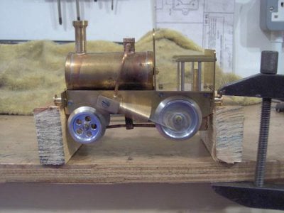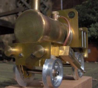
This locomotive design was by a model engineer called Dr. James R. Senft and the construction was detailed in 'Live Steam Magazine' in 1976.
The best description of the design, is given by the article itself :
"Dickins was inspired by a photograph of a British toy locomotive dating back to 1890. Although differing in mechanical detail, Dickins shares the general appearance of its larger antique toy prototype and consequently shares its quaint charm.................Dickins was designed to run on standard O-gauge toy track - the kind supplied with clockwork train sets - or on Lionel 027 track. The locomotive has ample power and speed for its class. It carries enough fuel and water for a 20 minute run pulling 2 tinplate cars around a 2ft-diameter circle of track, at a rate in excess of 2.5 feet per second."
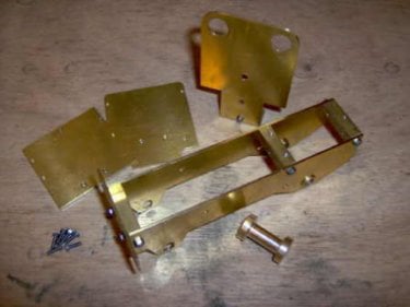
The plans specified steel for the frames but this build used brass, for easier working and so the model could be left unpainted.
This photograph shows all the frame components in a partly assembled state.
A combination of 8BA and 10BA hex head screws were used for the assembly. At this stage in production the rear wheel bushes had been located and a test with the rear axle showed that the frames were quite square and that the rear wheels could spin freely.
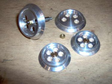
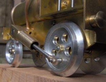
The wheels were made from Aluminium bar. They were made with 5 spoke holes instead of the 4 shown by the planes because the ML7 lathe could index 5 holes more accurately.
The rear (driving) wheels had one hole left out to allow room for the crank pin
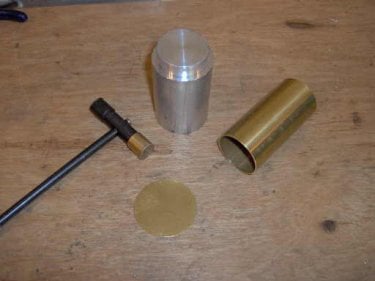
The boiler was made from a piece of 1.25" brass tube with some flanged end plates.
A former was turned from aluminium using the tube as a guide and with a rounded edge to help the forming
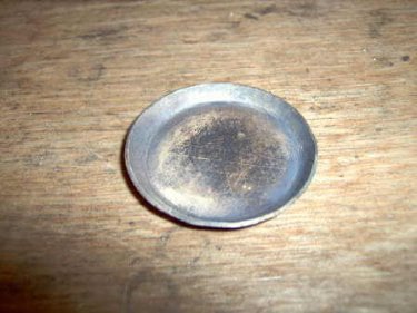
Two brass discs were hand cut and then annealed. They were progressively formed using a plastic hammer on the former with repeated annealing steps to keep the brass soft.
The finished end plates tested for size.
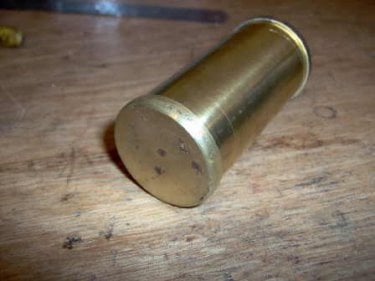
Once the bushes and mounting pin had been made, the whole boiler was brazed.
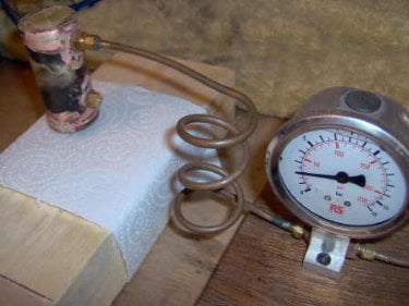
This image shows the boiler under a hydraulic test at 30psi (twice the working pressure). The tissue paper was used to locate any leaks.
The valve gear was of the oscillating type, as shown. All port drillings were made using the jig detailed in the plans, which gave working results first time.
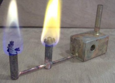
The burner was a simple 2-wick alcohol fuelled design, fabricated from bits of brass and copper. The hole through the side of the tank was to house the rear axle, which also acted as the support for the burner itself.
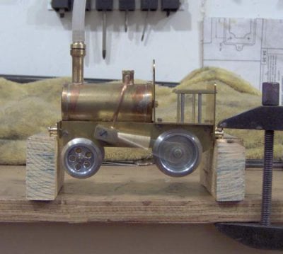
The engine was tested on compressed air to check the valve timing. The air hose was connected to the smokestack, in place of the safety valve and the compressor set to 10psi.
Initially there was a tight spot at one of the con-rod ends and so the hole was enlarged slightly to make the engine more free running. Then, after adding some light oil and a few turns of the wheel, it was off and running.
On the first steam test, the engine ran well - but not for long. Even with the water level quite low (allowing for more steam volume in the boiler) the engine would only run for about 15 seconds before slowing and stopping.
A new burner was made with larger wicks and larger bore fuel lines.
The larger burner would obviously reduce running time but should provide more heat to prevent steam exhaustion.
The second test made for continuous running of 7 minutes before the fuel was exhausted.
Here is a momentary video of the loco running in the back garden. Although great fun, it feels like a warning should be issued regarding fire, as it does pose a certain fire risk.
Numerous times the little locomotive has derailed on the corners and spilt meths has erupted into flames. This is OK outside but I would warn against using the loco indoors at speed.
Offline Website Software